
Bicycle chain with connected outer plates

a bicycle chain and outer plate technology, applied in the direction of driving chains, belts/chains/gearrings, chain elements, etc., can solve the problems of chain breaking, chain becoming weak, chain being subject to excessive force, etc., and achieve the effect of efficient operation

Inactive Publication Date: 2008-01-31
CURRAN SEAN
View PDF43 Cites 16 Cited by
  • Summary
  • Abstract
  • Description
  • Claims
  • Application Information

AI Technical Summary

Benefits of technology

[0003]The present invention meets this need by providing a chain unit that is strong enough to withstand impacts with objects that are encountered in the environment and that is sized to work efficiently in the chain unit.

Problems solved by technology

While the traditional design works well to transfer loads, one shortcoming of the chains known in the art is that the chains become weak when they are exposed to excessive forces.
However, modern bicycles are often used in environments where the chain comes into contact with objects in the environment at various angles and speeds, thereby subjecting the chain to excessive forces.
This causes the chain to break from the impact or to weaken to a point that it fails when a drive load is placed upon it.
Such damage endangers the rider.
The added weight is inefficient because it can impact the rider's performance.
Further, often times these larger chains do not fit well on sprockets.
In some instances, larger chains do not fit on the sprocket at all.
In fact, in recent years, sprockets have become smaller (i.e., they have fewer teeth), and as a result, large chains cannot make the tight bends.
Further, even when the larger chains do fit on the sprocket, the larger chains tend to wear the sprocket teeth down faster, thereby reducing the lifespan of the sprocket teeth.

Method used


Image

  • Bicycle chain with connected outer plates
  • Bicycle chain with connected outer plates
  • Bicycle chain with connected outer plates

Examples


Embodiment Construction

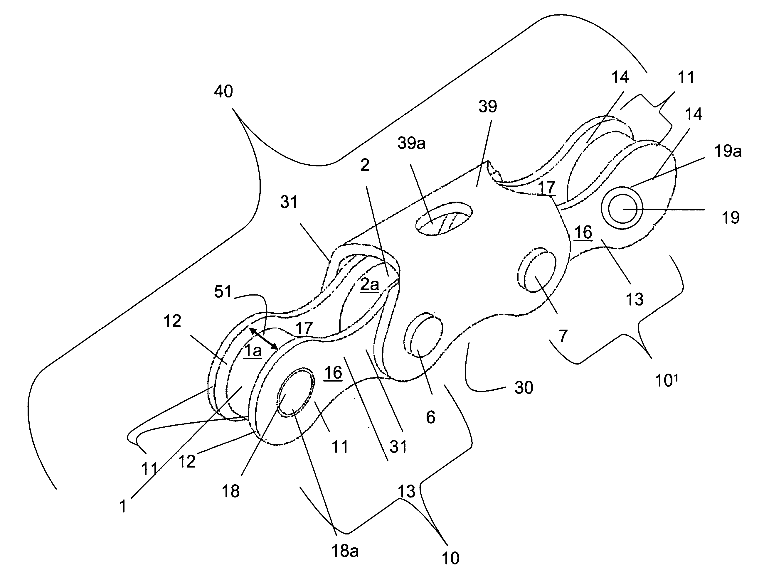
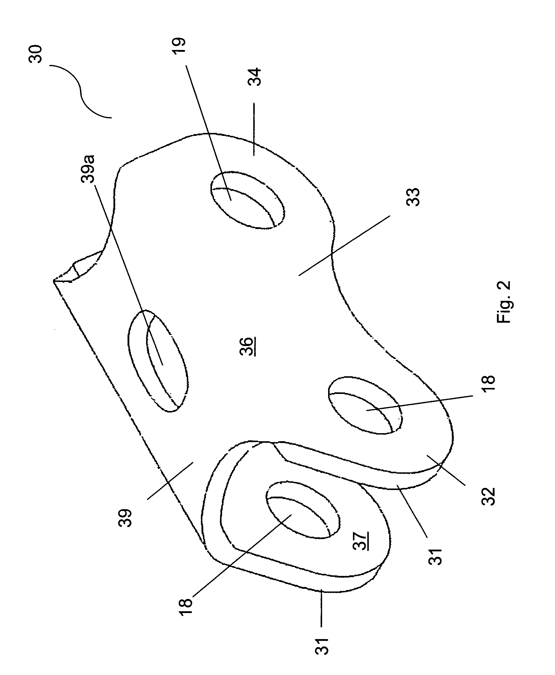
[0019]FIG. 3 shows an isometric view of an example of an embodiment of the claimed chain unit 40. In an embodiment, each chain unit 40 comprises two link units 10, 10′, a unitary outer plate 30, and first 6 and second 7 pins. Each link unit 10, 10′ comprises two inner plates 11, 11 and first 1 and second 2 rollers. Inner plates 11, 11 are made of steel or titanium. Inner plates 11, 11 are positioned substantially parallel to each other in first plane and are separated by a distance 51 therebetween. In an example, distance 51 is about 0.105-0.145 inches and is preferably about 0.125 inch (⅛ inch). In another example, distance 51 is about 0.074 to about 0.114 inch, and is preferably about 0.09375 inch ( 3 / 32 inch). Inner plates 11, 11 have first 16 and second 17 surfaces and first 18 and second 19 holes, respectively. Second surfaces 17 of the two inner 11, 11 plates of one link unit are opposed to each other. Each inner plate 11, 11 has first 12 and second 14 end regions and a solid ...


PUM


Abstract

The invention is a chain unit comprising first and second link units, a unitary outer plate, and first and second pins. Each link unit comprises two inner plates with two rollers positioned therebetween. The outer plate straddles and is secured to the link units. Outer plate comprises two walls and a bridge positioned therebetween that spans the tooth engaging space between link units. The unitary construction of the outer plate provides a structural integrity that prevents the plates from separating when the chain is exposed to force. A plurality of chain units can be linked together to form a chain.

Description

FIELD OF INVENTION[0001]The invention relates to chain units and particularly to chain units having a unitary outer plate.BACKGROUND OF INVENTION[0002]Standard bicycle chains are primarily designed to transfer and handle drive loads to the back wheel. While the traditional design works well to transfer loads, one shortcoming of the chains known in the art is that the chains become weak when they are exposed to excessive forces. However, modern bicycles are often used in environments where the chain comes into contact with objects in the environment at various angles and speeds, thereby subjecting the chain to excessive forces. If an object contacts the chain at an angle that is not in line with the drive direction, the outer plates of the chain can bend and pull from the pin. This causes the chain to break from the impact or to weaken to a point that it fails when a drive load is placed upon it. Such damage endangers the rider. Bicycle chains known in the art have tried to address t...

Claims


Application Information

Patent Timeline
Patent Type & Authority Applications(United States)
IPC IPC(8): F16G13/02
CPCF16G13/06
Inventor CURRAN, SEAN
Owner CURRAN SEAN
Learn More