Method And Apparatus Of Dynamic Channel Assignment For A Wireless Network

a wireless network and dynamic channel technology, applied in the field of dynamic channel assignment for wireless networks, can solve the problems of poor performance, simple fca method, and mutual interference between aps

Active Publication Date: 2008-01-24
IND TECH RES INST
View PDF15 Cites 12 Cited by
  • Summary
  • Abstract
  • Description
  • Claims
  • Application Information

AI Technical Summary

Benefits of technology

[0008]The present invention has been made to overcome the above-mentioned drawback of conventional channel assignment methods, which provides a method and apparatus of dynamic channel assignment for a wireless network. By using a normal graph, the present invention provides a fully-distributed and low complexity DCA technology for a non-uniformly-distributed wireless network.
[0009]Based on the frame of the normal graph, the present invention uses the available subscriber position information to define soft information to reflect the local traffic condition. Then, the soft information is exchanged between the AP and the subscriber repeatedly, and a standard process is used to repeatedly optimize the channel assignment in the wireless network. The result greatly improves the network throughput. The present invention further adopts the notion of subscriber exclusive region (SER) to guarantee the link quality between each subscriber and the AP.
[0012]In comparison of the present invention and the two commonly used conventional methods, namely, fixed angular channel assignment and space-division multiple access (SDMA), the present invention can serve more subscribers by increasing the system capacity 30-200% under the same bit error rate (BER).

Problems solved by technology

Under such circumstances, if a nearby AP uses the same frequency, the mutual interference will exist between the APs.
The FCA method is simple, yet suffers poor performance when the traffic is non-stationary or non-uniform.
The conventional DCA has the problems of higher complexity and requiring to feedback a large amount of channel state information.
Unfortunately, to provide service to the subscribers around the hot spot, the placement of APs in the WLAN is always non-uniformly distributed.
Even worse, it is not easy to measure the CIR at the receiving end, and higher CIR does not account for good service quality before the antenna beam forming and frequency equalization.

Method used


Image

  • Method And Apparatus Of Dynamic Channel Assignment For A Wireless Network
  • Method And Apparatus Of Dynamic Channel Assignment For A Wireless Network
  • Method And Apparatus Of Dynamic Channel Assignment For A Wireless Network

Examples


Embodiment Construction

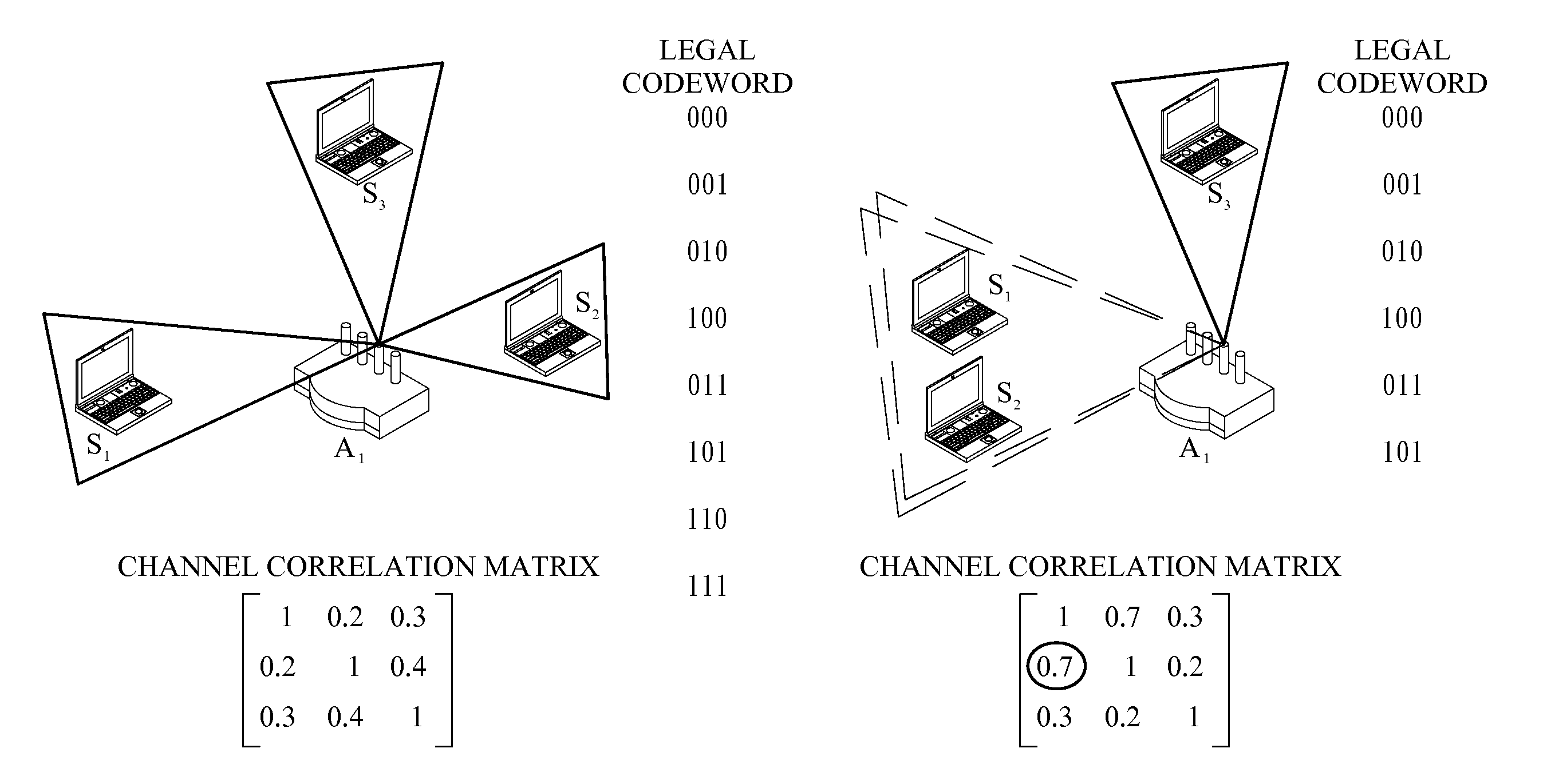
[0021]The normal graph was originally used in the decoding process in a communication system. By observing the log-likelihood ration (LLR) exchange in a normal graph and the characteristics of normal graph discrete operation, the present invention transforms a complicated DCA problem into a decoding problem.

[0022]The present invention observes that as long as a normal graph framework can be used to model the DCA problem, the local rule for all the nodes in the normal graph are well-defined and uses the message-passing through the pre-assigned local agents, the DCA problem can be easily solved with a standard process.

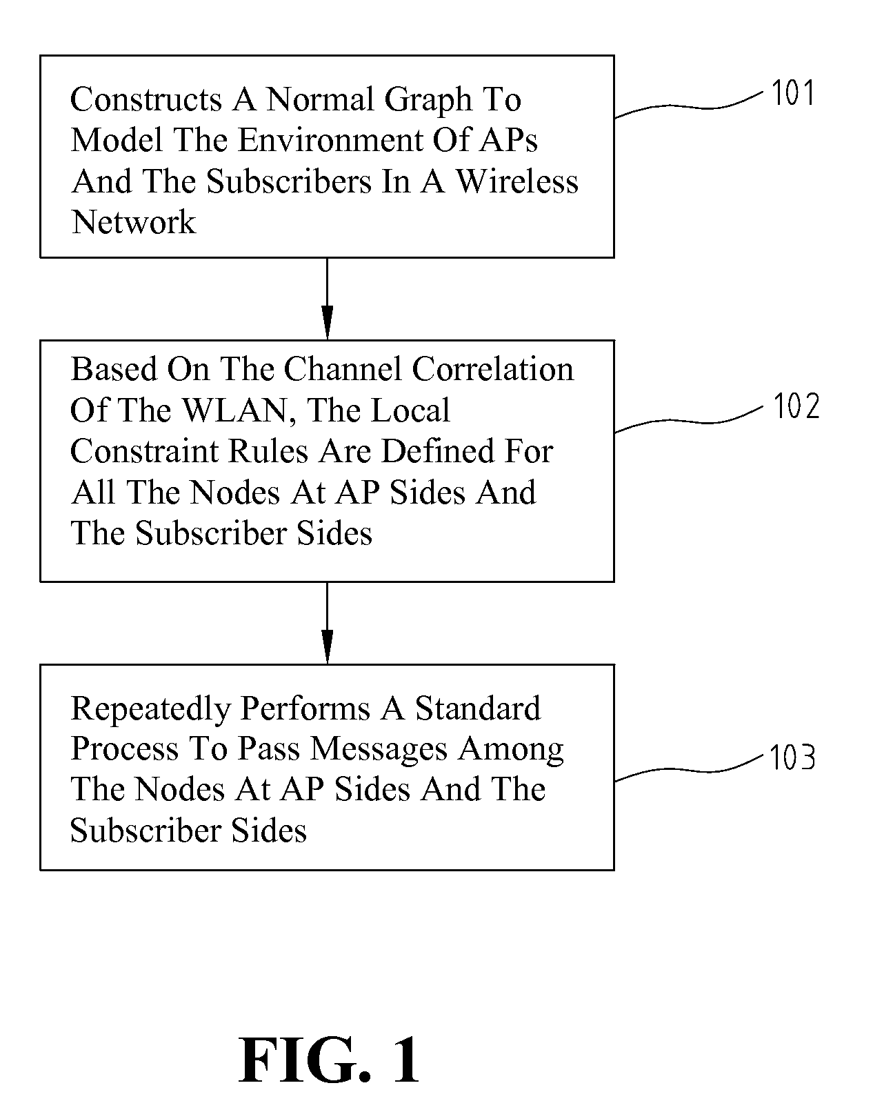
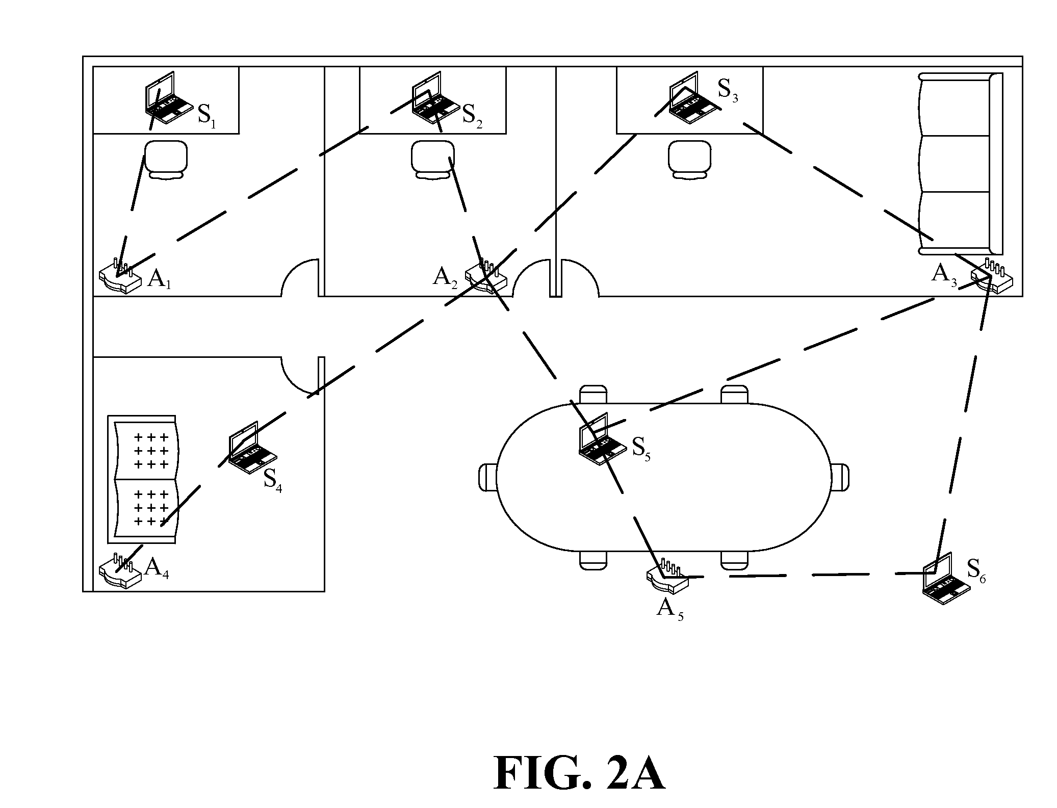
[0023]FIG. 1 illustrates the operating steps of the DCA method according to the invention. As shown in step 101, the method constructs a normal graph to model the environment of APs and the subscribers in a wireless network. The normal graph includes a plurality of nodes at AP sides, a plurality of nodes at subscriber sides, and a plurality of edges. The normal graph is ...


PUM


Abstract

Disclosed is a method and apparatus for dynamic channel assignment (DCA) in a wireless network, which describes the complex channel assignment problem with a decoding problem. The invention describes the decoding problem with a normal graph and specifies all the local rules enforced by all the nodes at access point sides and subscriber sides. Then, the invention carries out the sum-product algorithm to solve the DCA. It is not only a fully-distributed low-complexity DCA technology, but also significantly increases the network throughput. The invention further adopts the concept of subscriber exclusive region to guarantee the link quality between a subscriber and an access point.

Description

FIELD OF THE INVENTION[0001]The present invention relates to a method and apparatus of dynamic channel assignment for a wireless network.BACKGROUND OF THE INVENTION[0002]As the demands on the versatile wireless communication service, such as voice, data and multimedia, increases rapidly, the wireless local area network (WLAN) also grows fast. To meet the ever-growing demands, more and more wireless nodes are used in addition to the wireline service. As the technology matures and the cost reduced, WLAN is gaining popularity.[0003]In a WLAN, an access point (AP) is usually individually set up without the overall planning. Under such circumstances, if a nearby AP uses the same frequency, the mutual interference will exist between the APs. Therefore, it is imperative to prevent such interference and maintain a high carrier-to-interference ration (CIR) to guarantee the high data rate.[0004]In recent years, a multiple-input-multiple-output (MIMO) multi-user technology is developed. This t...

Claims


Application Information

Patent Timeline
Patent Type & Authority Applications(United States)
IPC IPC(8): H04Q7/28H04W16/10
CPCH04W16/10H04W16/22H04W28/04H04B17/391H04W72/04H04W88/08H04W28/18
Inventor WU, CHENG-HSUANCHEN, JIUNN-TSAIR
Owner IND TECH RES INST
Why Eureka
Try Eureka