Eureka AIR delivers breakthrough ideas for toughest innovation challenges, trusted by R&D personnel around the world.

High leverage bolt cutter

a bolt cutter and high-leverage technology, applied in the direction of metal working devices, etc., can solve the problems of limiting the ability of the tool to accept a large workpiece between the jaws, increasing the cost, and user having to remove his hand from the handl

Inactive Publication Date: 2008-01-24
ALLTRADE TOOLS
View PDF42 Cites 13 Cited by
  • Summary
  • Abstract
  • Description
  • Claims
  • Application Information

AI Technical Summary

Benefits of technology

[0008]In yet other detailed aspects, the second lever further includes a second channel having a bottom portion, two opposing side portions extending from the base portion, a second pivot pin connecting the two side portions, and a third pivot pin connecting the two side portions and spaced apart from the second pivot pin, the second pivot pin configured to engage the second pivot of the moveable workpiece engagement member, the third pivot pin configured to engage the third pivot of the linkage. In further aspects, the linkage includes a tab portion, the tab portion having a stop surface disposed at a distance from a line defined by the third and fourth pivots of the linkage, the distance selected such that the stop surface abuts the bottom portion of the second channel to limit movement of the second lever toward the first lever, thereby preventing the second ...

Problems solved by technology

A disadvantage of prior designs is that a user must remove his hand from the handle in order to rotate the screw-type adjustment device.
That is, the handles of many high leverage cutting tools must be moved a great distance in order produce a slight movement in the jaws, which limits the ability of the tool to accept a large workpiece between its jaws.
Double-action cutters have been designed to cut large workpieces; however, double-action cutters involve more parts than single-action cutters, which increases cost.

Method used


Image

  • High leverage bolt cutter
  • High leverage bolt cutter
  • High leverage bolt cutter

Examples


Embodiment Construction

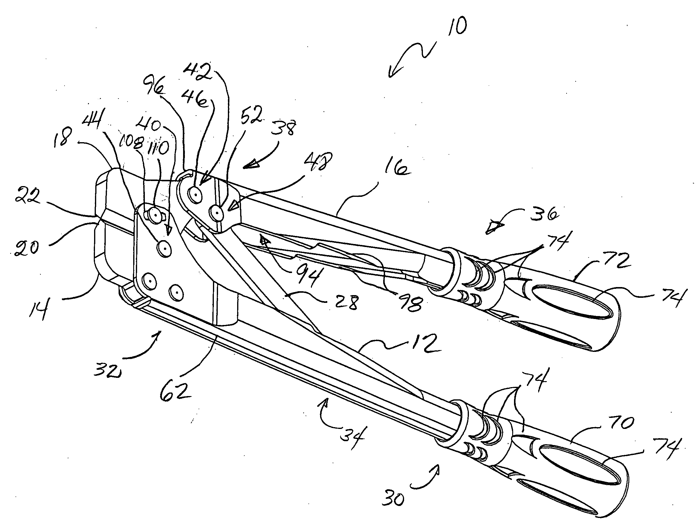
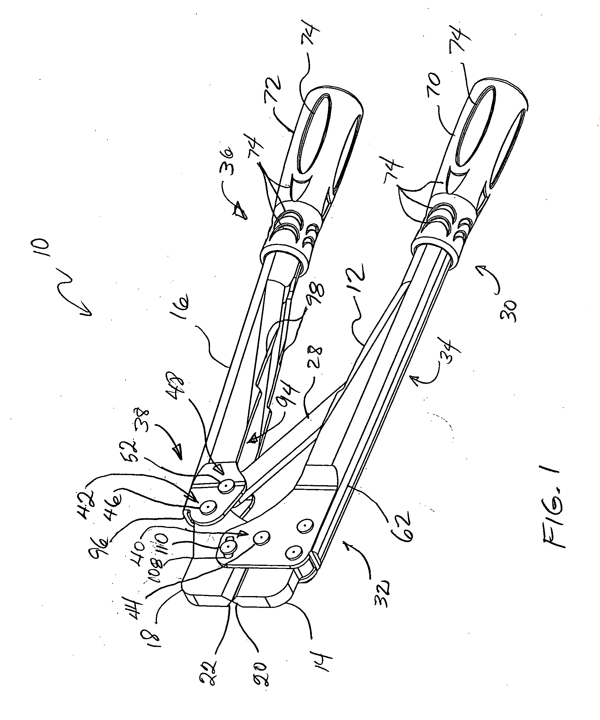
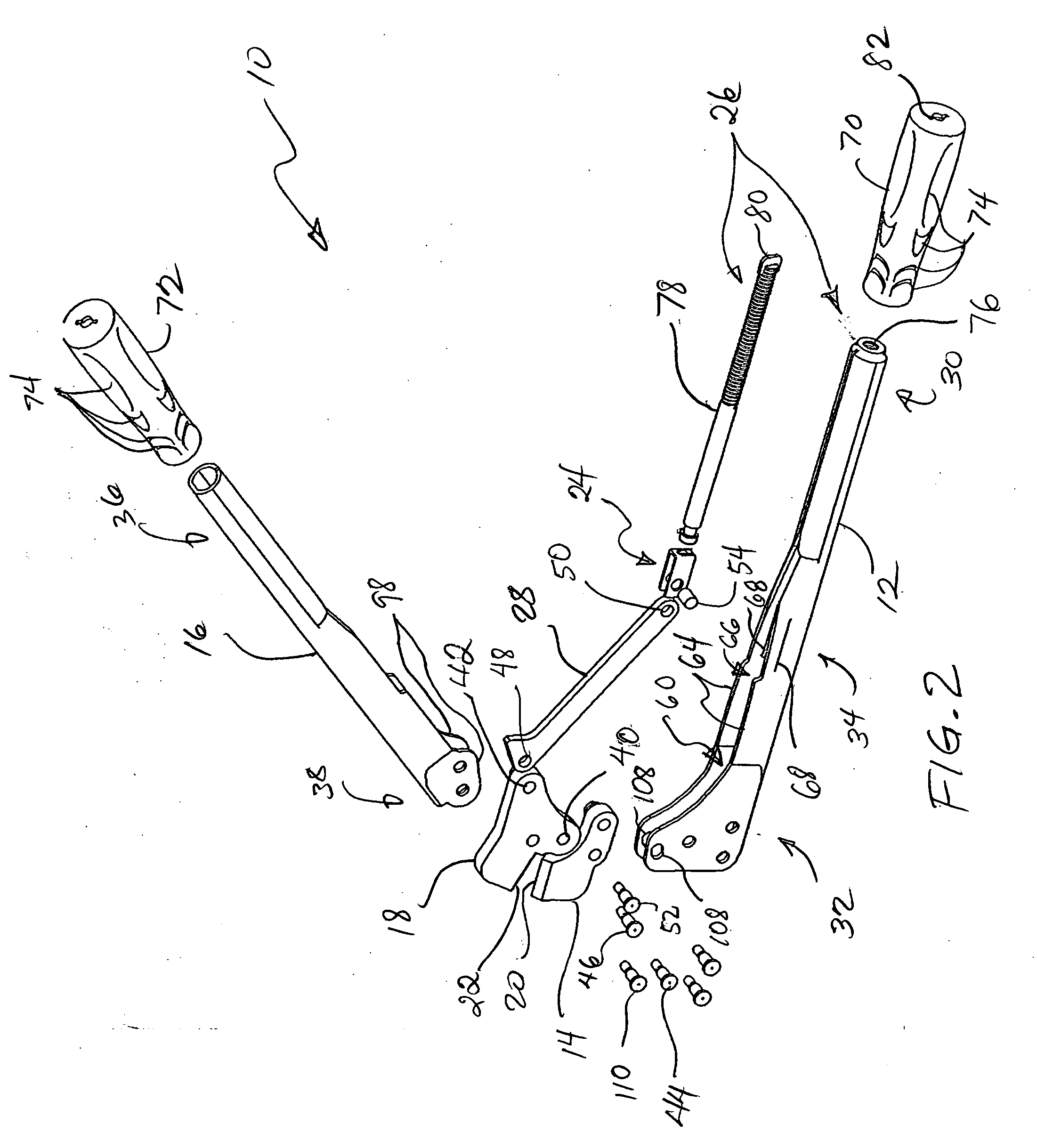
[0023]Referring now in more detail to the exemplary drawings for purposes of illustrating embodiments of the invention, wherein like reference numerals designate corresponding or like elements among the several views, there is shown in FIGS. 1 and 2 a tool 10 comprising an elongate first lever 12, a first workpiece engagement member 14 connected to the first lever, an elongate second lever 16, a second workpiece engagement member 18 pivotably connected to the second lever, cutting edges 20, 22 formed on the first and second workpiece engagement members, a slide element 24 (FIG. 2), an adjustment device 26 (FIG. 2), and a linkage 28. The first lever includes a first rear portion 30, a first front portion 32, and a medial portion 34 disposed between the first front portion and the first rear portion. The second lever includes a second rear portion 36 and a second front portion 38.

[0024]With continued reference to FIGS. 1 and 2, the second workpiece engagement member 18 is located adja...


PUM


Abstract

A cutting tool includes a first and second pivoted levers for opening and closing and a pair workpiece engagement members having one or more cutting edges. One of the workpiece engagement members is pivotably attached to the fist and second members, while the other workpiece engagement member is fixedly attached to the second lever. The levers connected together by a linkage having one end fixed in position the first lever and having another end slideably attached to the second lever by of a slide element. An adjustment device is connected to the side element and to a rotatable handle on the first handle. The adjustment device moves and holds the slide element in a plurality of positions which correspond to different cutting ratios. An associated method of use is also disclosed in which the rotatable handle is used to adjust the cutting ratio while the tool is engaged with a workpiece.

Description

FIELD OF THE INVENTION[0001]The invention relates generally to cutting tools and, more particularly, to an adjustable cutting tool with hinged handles and a pivoting blade.BACKGROUND OF THE INVENTION[0002]Conventional cutting tools are generally made up of two handles connected to a pair of opposing jaws or workpiece engagement members which can be manually separated or brought together by movement of the handles. The connection of the handles to the jaws can be designed to create increased leverage and, thus, greater cutting force. A prior design makes use of a four-bar mechanism, where the two handles make up two of the bars, one of the jaws makes up a third bar, and linkage makes up a fourth bar. A screw-type adjustment device may be used to move the arm or linkage along one of the handles for the purpose of altering the effective length of the third bar. By altering the length of the third bar, the leverage of the tool may be adjusted. A disadvantage of prior designs is that a u...

Claims


Application Information

Patent Timeline
IPC IPC(8): B26B17/00
CPCB26B17/02
Inventor HERNANDEZ, HECTOR R.HILLINGER, GEORGE
Owner ALLTRADE TOOLS
Why Eureka
Eureka Blog
Learn More