
Hypodermic injection system

a technology of hyperoderm and injection system, which is applied in the direction of infusion syringes, transportation and packaging, liquid transfer devices, etc., can solve the problem of not having the option of conventional compressed gas, and achieve the effect of reducing cost and reducing the risk of contamination

Active Publication Date: 2008-01-17
DANTONIO CONSULTANTS INT INC
View PDF25 Cites 37 Cited by
  • Summary
  • Abstract
  • Description
  • Claims
  • Application Information

AI Technical Summary

Benefits of technology

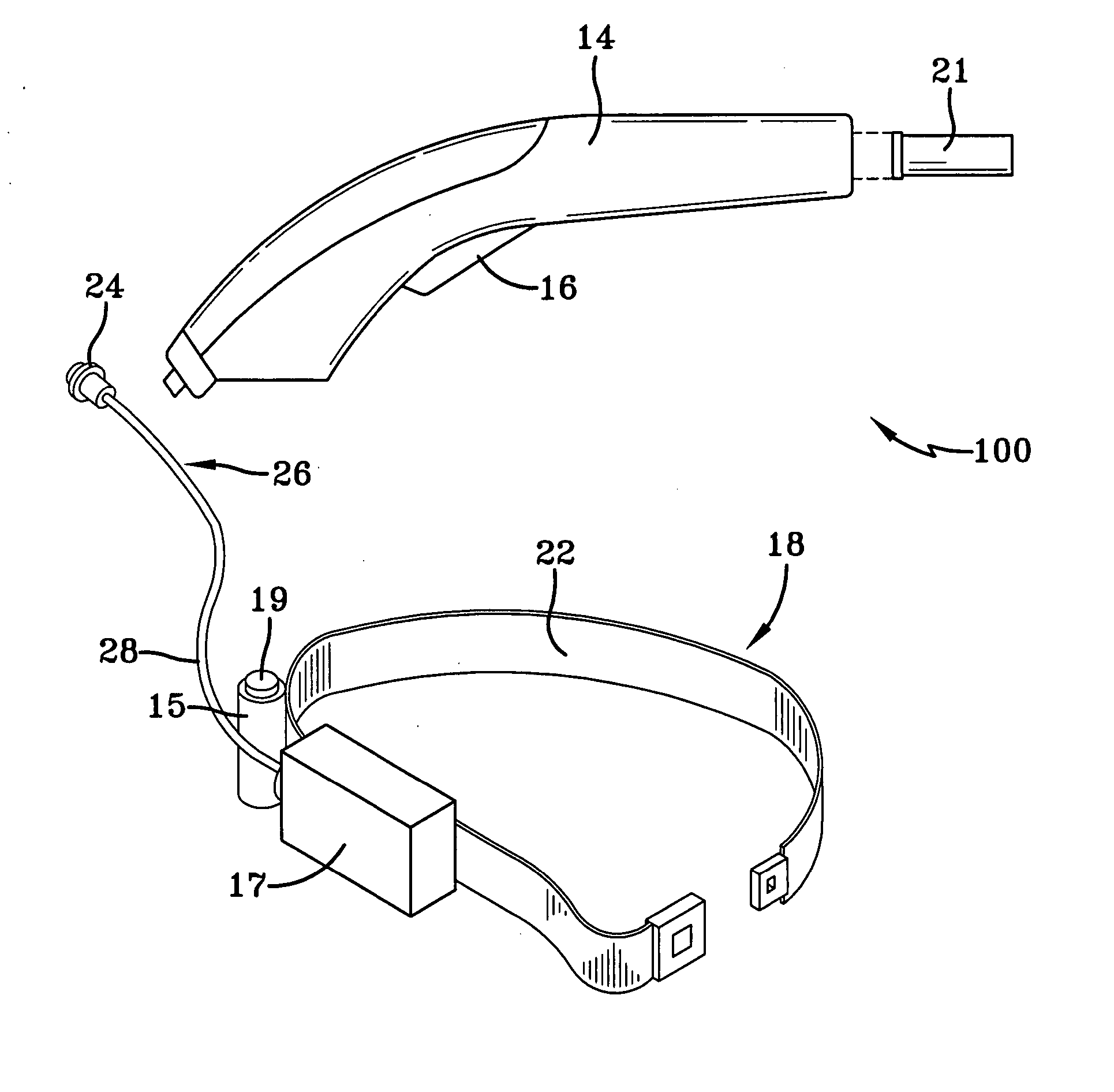
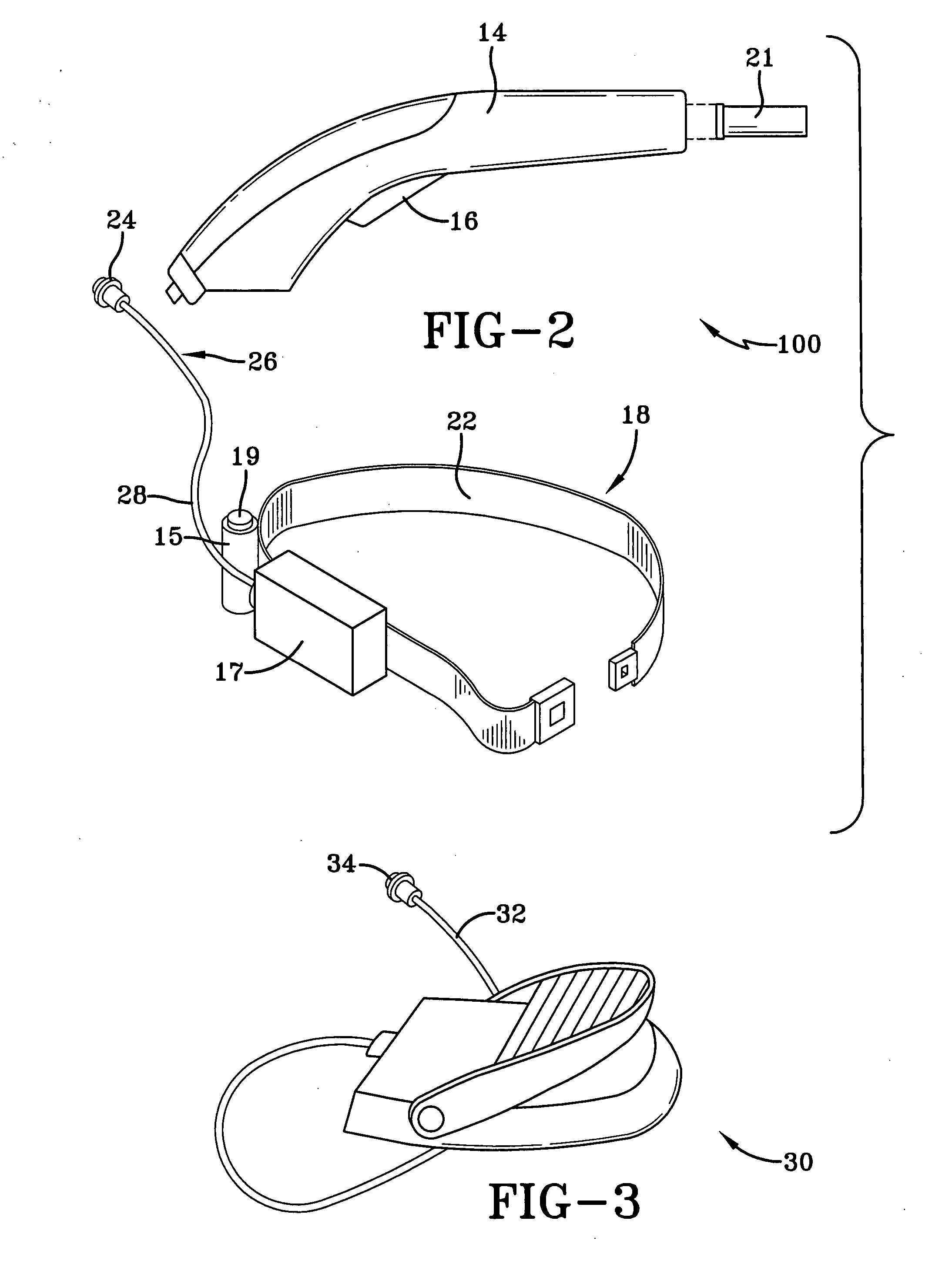
[0010] The object of this invention is to provide a new, high-speed injection system that is economical, technically suited to campaigns for mass immunization and meets the needs of reliability, ergonomics, power availability, cost, safety and effective injections. The system is designed with several options for both powered and manual operation so that the needs of a wide variety of users can be met, these to include clinical and personal use injection systems. One option for powering the injector is an embodiment wherein a motor is remote from the handpiece discussed below, and referred to as a “Motor-Off Tool” (MOT) “Handpiece” with three methods including both electrical and manual means for compressing the injection spring. Also available is another embodiment wherein a motor is included in the handpiece, and referred to as a “Motor-In-Tool” (MIT) “Handpiece” similar to that reported in earlier disclosures by at least one of the inventors; however, according to a preferred embodiment in this disclosure, rather than a rotating cam mechanism for compressing the energy storage spring, a gear reduction and ball screw are used to do the same thing which provides novel methods and advantages for operating the motor in both the forward and reverse directions. For example, motor reversal allows for increasing the speed of rapid, repetitive injections by compressing the injection spring in one direction and then reversing direction for an immediate return to the starting point in preparation for the next arming cycle regardless of whether or not the present injection is delivered. An internal switching arrangement determines when the motor drive reaches the intended location, then provides an appropriate signal to first stop, latch the spring, and then reverse motor direction at the appropriate time. This sequence of repeated motor reversal takes place for every injection cycle, the distance of travel in each direction being determined by the volume of injectate to be delivered. In every case described, the mass immunization kit will also include a means for manual delivery if necessary; and this system has utility as a manual device for clinical situations.
[0011] In an alternate embodiment, the forward direction of the motor allows for the ball screw drive to completely eliminate the energy storage injection spring by using a direct drive delivery from the motor to the ampule piston. One of the advantages of direct drive is the ability to provide an ever-increasing drive voltage to the motor that, in turn, will yield a profile of increasing pressure over the course of an injection. This increasing pressure will drive the injectate ever deeper, rather than ever more shallow, which will discourage the inclination of medication being left on the surface as is sometime seen with the usual spring driven, orifice oriented systems. This feature is especially useful for personal use injectors used by diabetics who are often very sensitive to the correct amount of insulin entering the body. Availability of reversing motor direction can also be used for filling an empty ampule, and has particular utility with personal use injectors as an improvement to the tedious manual methods now in use. To do this, the injector ram will first grab the plunger of an empty in-dwelling ampule, and then, with a push button command by the user, the injector will pull the plunger back to draw vaccine from a supply connected to the front end of the ampule. Mechanical or magnetic means can be used to make this connection to the ampule piston. Once the ampule is full by virtue of the reverse direction, a low speed button controlled motor drive will allow the vaccinator to slowly “jog” the piston forward, and visually determine when all air is expelled from the ampule. For direct drive delivery, the motor is then transferred to its high-speed mode to drive the injectate into the injection site.
[0013] Also disclosed are means for an on site mixing of pre-filled individual ampules having lyophilized medication in one compartment, and its mixing diluent in a companion compartment, the two being separated by an appropriate barrier. Several means are shown for utilizing a barrier between the medication and its diluent. The barrier can be frangible or a one-way valve. In one embodiment, a filling station will provide sufficient force for filling the individual ampules with pre-mixed liquid vaccine through the exit nozzle, an option that is also useful for the personal use injectors described above. This approach for front end filling will virtually eliminate the problem of having air enter the chamber that usually occurs when filling ampules by creating a vacuum when drawing back on the plunger. Alternatively, the filling station can provide sufficient force to insert the diluent through the exit nozzle and then mix it with lyophilized medication located in the ampule.
[0014] A new concept of a mixing magazine allows for simultaneous, on-site mixing of an entire magazine full of the pre-filled, lyophilized / diluent cartridges. In this case, the magazine can also be used as the shipping container from the manufacturer to anywhere in the world thus, of course, lowering cost and further reducing the risk of contamination due to intermediate handling.

Problems solved by technology

This option is not available with conventional compressed gas, CO2 or ignitable gas drive systems.

Method used


Image

  • Hypodermic injection system
  • Hypodermic injection system
  • Hypodermic injection system

Examples


Embodiment Construction

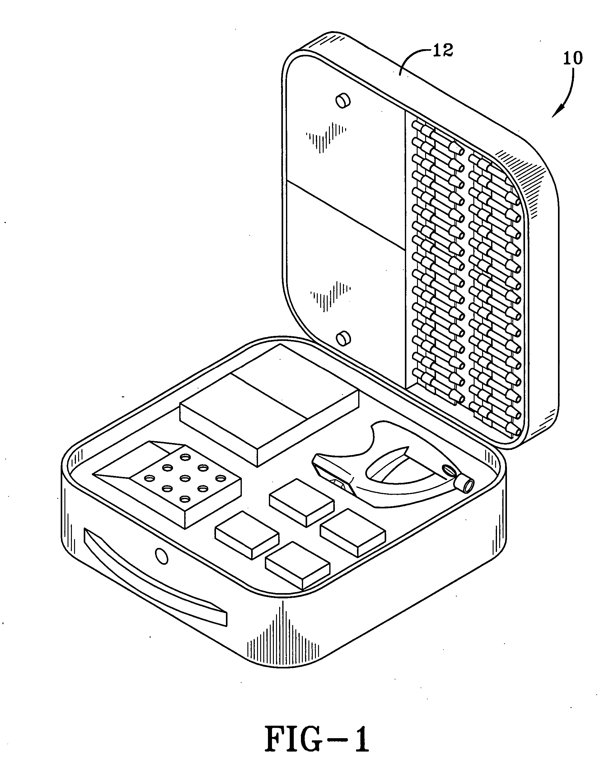
[0062]FIG. 1 illustrates a customized, all-inclusive, carrying case 12 for the portable injection system, station or kit 10 according to an embodiment of the invention. Each carrying case 12 of the portable system 10 contains all components necessary for a healthcare team to efficiently administer thousands of injections at the rate of up to 600 people per hour, this equipment to include several magazines, at least one handpiece, enough battery power for the number of injections expected, manual arming means if needed, at least one filling system, several battery charging options and simple tools to effect repairs to the system components.

[0063] The case has retractable legs (not shown) for standing the unit in an upright position and flat panels from the four sides that can be pulled out to form a working surface (not shown) for the healthcare team if no other surfaces are available or convenient. Sterile components such as gauze, cotton balls, band-aids, etc., will also be housed...


PUM


Abstract

A hypodermic injection system particularly for use in mass immunizations having a handpiece with a grasping mechanism for holding ampules filled with injectate, a plunger for driving into the ampule to discharge the injectate in an injection process, an injection spring mechanism for driving the plunger, a motor and / or manual mechanism for cocking the injection spring mechanism, and an ampule ejection mechanism for ejecting ampules after use under control of a release mechanism. Ampules can be loaded, used and ejected without contact by the user of the system or the patient being injected. Also disclosed are a filling station for filling ampules through their injection orifices, and an arming device for setting the injection spring. Ampules are disclosed having a piston which is drivable towards an orifice to discharge injectate through the orifice. Ampules are also disclosed having enlarged proximal portions for easy grasping by the grasping mechanism of the injector. Ampules are further disclosed with separators for mixing lyophilized medication and a diluent. Further disclosed are magazines for holding ampules for sequential use by the hypodermic injector. The disclosed system finds particular use as a mass immunization kit for making numerous injections in the field.

Description

CROSS REFERENCE TO RELATED APPLICATIONS [0001] This application is a division of U.S. patent application Ser. No. 10 / 224,034 filed Aug. 20, 2002, and claims the benefit of U.S. provisional patent applications Ser. No. 60 / 313,978 filed Aug. 21, 2001 and Ser. No. 60 / 358,861 filed Feb. 22, 2002.BACKGROUND OF THE INVENTION [0002] 1. Field of the Invention [0003] This invention relates to hypodermic injection systems, and in particular to those residing in a kit format. It more particularly relates to hypodermic injection systems in kit form for mass inoculations, using electrical or manual power. The invention additionally relates to hypodermic injection systems having ampules that are processed to avoid cross contamination. [0004] 2. Description of the Prior Art [0005] Many forms of hypodermic injection systems are available. These systems include rapid delivery of vaccines / medications with jet injectors that utilize the same orifice for every injection, and in some cases, use individu...

Claims


Application Information

Patent Timeline
Patent Type & Authority Applications(United States)
IPC IPC(8): A61M5/00A61D1/02A61M5/24A61M5/30B67D7/02B67D7/58
CPCA61D1/025A61M5/002A61M5/1782A61M2209/086A61M5/30A61M2005/005A61M5/2448A61M5/001
Inventor D' ANTONIO, NICHOLAS F.COLVIN, RICHARD O.D' ANTONIO, LINDA F.
Owner DANTONIO CONSULTANTS INT INC
Learn More