
Image Forming Apparatus and Image Forming Method

a technology of image forming apparatus and forming method, which is applied in the direction of electrographic process, instruments, transportation and packaging, etc., can solve the problems of deteriorating binding quality, and achieve the effect of improving binding quality

Inactive Publication Date: 2008-01-17
CANON KK
View PDF33 Cites 3 Cited by
  • Summary
  • Abstract
  • Description
  • Claims
  • Application Information

AI Technical Summary

Benefits of technology

The invention aims to improve the binding quality of image data on paper by making the width of blank portions constant and avoiding differences in the blank area between different papers. This is achieved by an image forming apparatus that includes an image forming means for visualizing image data and forming it onto transfer materials, a post-processing means for executing a post-process including a stapling process, a folding process, and / or a sorting process in order to execute a binding process to the transfer materials on which the image data has been formed, and a trimmer for executing a trimming process to a bundle of the transfer materials subjected to the binding process by the post-processing means. The image forming means sets a non-image forming area including a processing portion to which the trimming process is executed and a valid image forming area excluding the non-image forming area onto the transfer material and forms the image data into the valid image forming area of the transfer material.

Problems solved by technology

The above conventional image forming system, however, has a problem such that if the sheets of paper subjected to the binding process by the post-processing apparatus are further subjected to the cutting process by using the trimming apparatus, a distance between a paper edge of the paper in a paper bundle obtained after completion of the cutting process and an image forming area, that is, a width of blank portion differs every paper and is not constant, so that binding quality deteriorates.

Method used


Image

  • Image Forming Apparatus and Image Forming Method
  • Image Forming Apparatus and Image Forming Method
  • Image Forming Apparatus and Image Forming Method

Examples


Embodiment Construction

[0022] An embodiment of the invention will be described hereinbelow with reference to the drawings.

(Whole Construction)

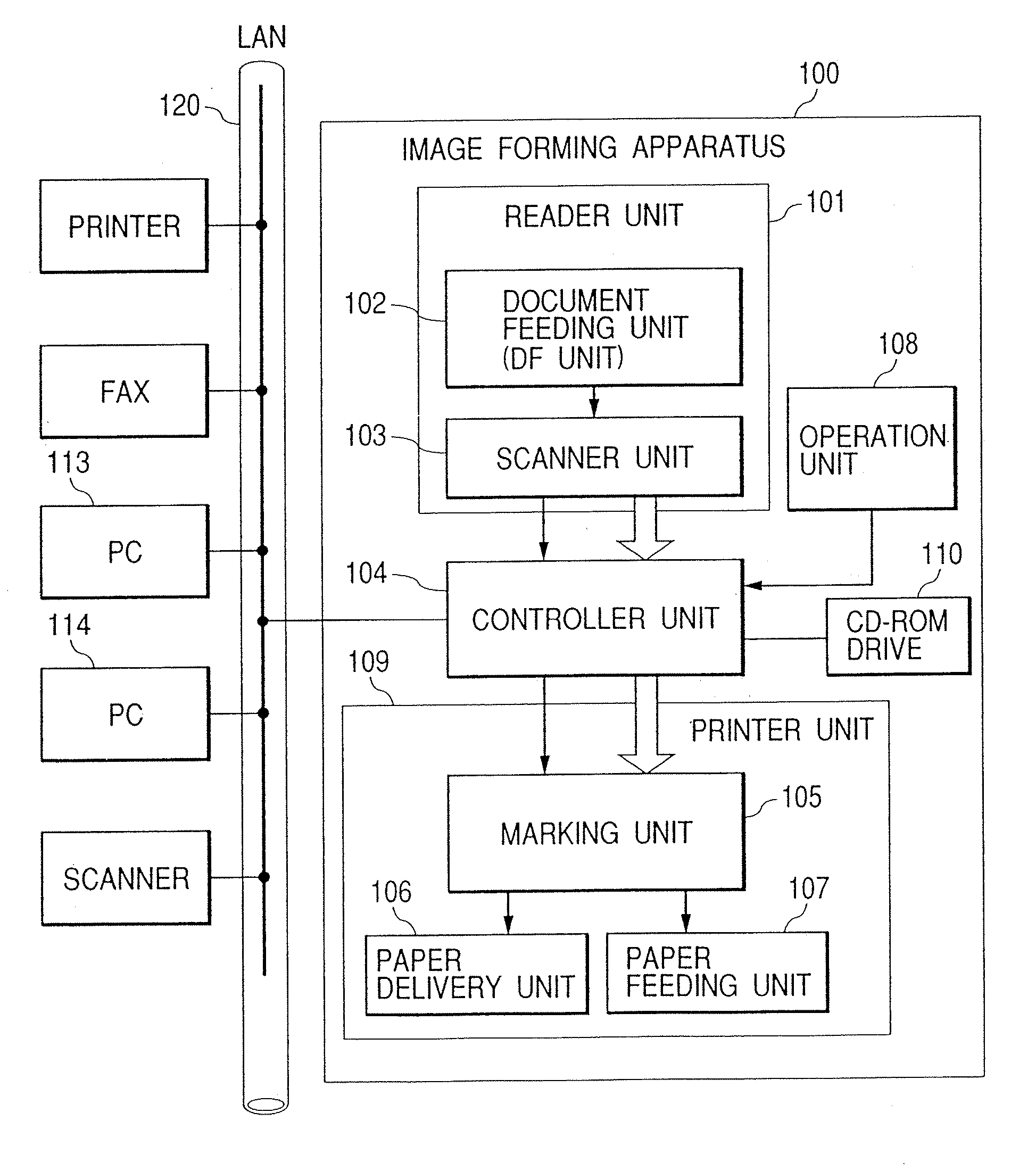
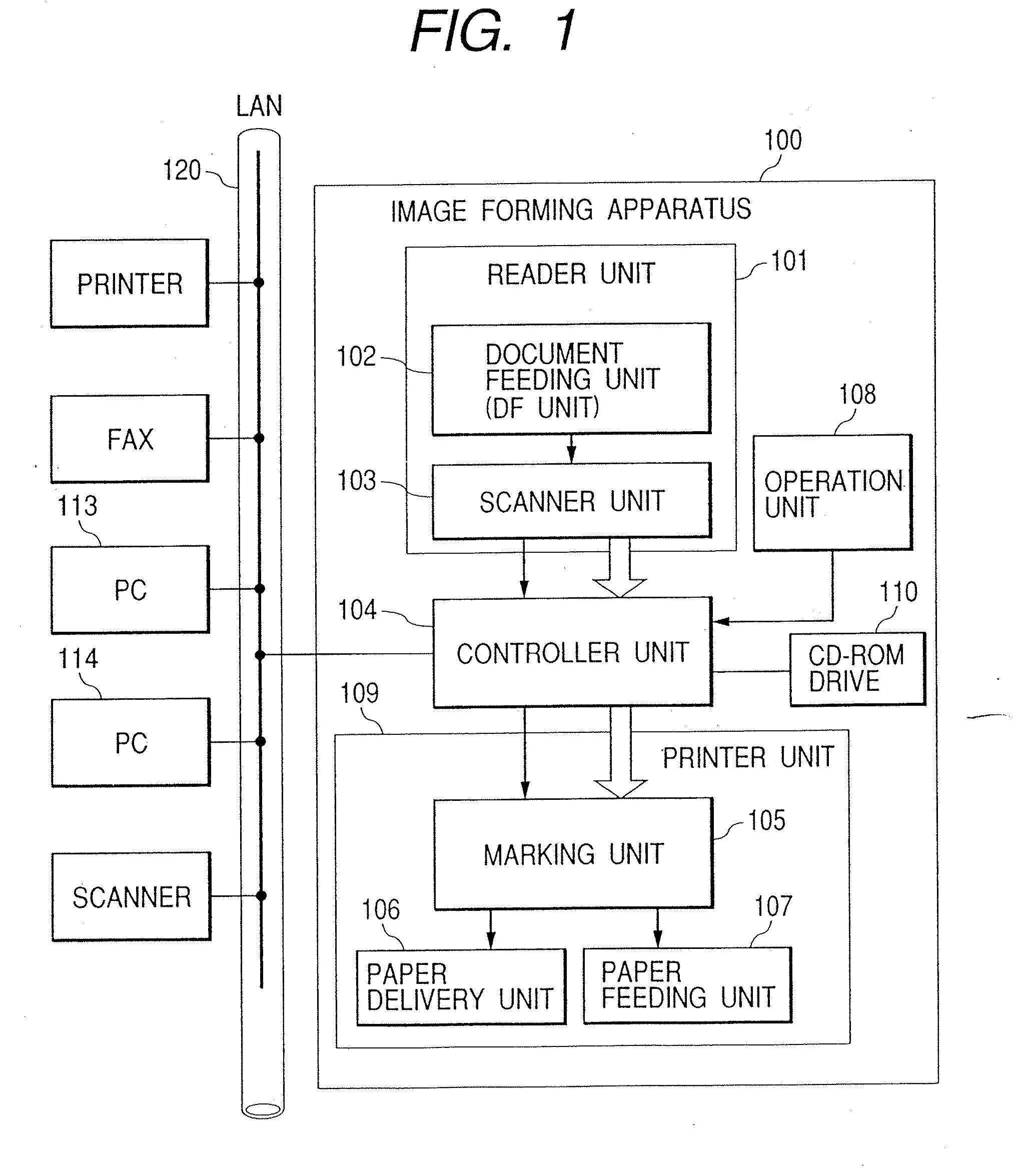
[0023]FIG. 1 is a block diagram showing a whole construction of an image forming apparatus according to the embodiment of the invention.

[0024] An image forming apparatus 100 is connected to a plurality of host computers (in the embodiment, first and second host computers 113 and 114) via a LAN (Local Area Network) 120 such as Ethernet® or the like.

[0025] That is, the image forming apparatus 100 is constructed by: a reader unit 101 for executing a reading process of image data; a printer unit 109 for executing an outputting process of the image data; an operation unit 108 having a keyboard for executing the input / output operation of the image data and a liquid crystal panel for executing a display of the image data and various functions, or the like; a CD-ROM drive 110 to which a CD-ROM in that a control program, the image data, and the like have previously been...


PUM


Abstract

An image forming apparatus having: image forming means for visualizing image data read out by image reading means and forming it onto transfer materials; post-processing means for executing a post-process including a stapling process, a folding process, and / or a sorting process in order to execute a book-binding process to the transfer materials on which the image data has been formed; and a trimmer for executing a trimming process to a bundle of the transfer materials subjected to the binding process by the post-processing means, wherein when the trimming process by the trimmer is executed, the image forming means sets a non-image forming area including a processing portion to which the trimming process is executed and a valid image forming area excluding the non-image forming area onto the transfer material and forms the image data read out by the image reading means into the valid image forming area of the transfer material.

Description

BACKGROUND OF THE INVENTION [0001] 1. Field of the Invention [0002] The invention relates to an image forming apparatus or the like such as a copying apparatus or the like and, more particularly, to an image forming apparatus or the like to which a post-processing apparatus and a trimming apparatus are attached and which can execute a binding process. [0003] 2. Related Background Art [0004] Hitherto, there has been known an image forming system in which, to an image forming apparatus for reading an image of an original and forming the read image onto a transfer material (paper), a post-processing apparatus for executing a binding process such as stapling process, folding process, sorting process, and the like to the paper on which the image has been formed and a trimming apparatus for executing a cutting process to the sheets of paper subjected to the binding process by the post-processing apparatus are attached. [0005] By attaching such post-processing apparatus and trimming appara...

Claims


Application Information

Patent Timeline
Patent Type & Authority Applications(United States)
IPC IPC(8): G03G15/00B65H37/00G03G21/00G03G15/047G03G15/36G06T3/20H04N1/387
CPCG03G15/047G03G15/50G03G15/6541G03G2215/00586H04N1/3875G03G2215/00827G03G2215/00877G03G2215/00936G03G2215/00814
Inventor KAWAHIRA, AKIKO
Owner CANON KK
Learn More