
Optical fiber, manufacturing method of the same, and optical amplifier

a manufacturing method and optical amplifier technology, applied in the field of optical amplifiers, can solve problems such as transmission performance degradation, and achieve the effects of suppressing fwm, reducing amplification efficiency, and shortening the length of the fiber

Inactive Publication Date: 2008-01-17
FUJITSU LTD
View PDF12 Cites 3 Cited by
  • Summary
  • Abstract
  • Description
  • Claims
  • Application Information

AI Technical Summary

Benefits of technology

The present invention relates to an optical fiber, a manufacturing method of the same, and an optical amplifier for use in a Wavelength Division Multiplex (WDM) transmission system. The invention aims to improve transmission performance by decreasing the interaction length of Four Wave Mixing (FWM) crosstalk, which is a nonlinear effect that occurs in the EDF of an optical amplifier. To address this problem, the invention proposes a technique to decrease the EDF length while maintaining a constant Erbium ion concentration. This technique can be used in a WDM transmission system with a decreased wavelength interval between signals, allowing for a larger transmission capacity.

Problems solved by technology

On the other hand, there has been a problem that an increased length of the EDF can results in a greater influence of a crosstalk due to Four Wave Mixing (FWM), which is a nonlinear effect occurring in the EDF, leading to deterioration of transmission performance.

Method used


Image

  • Optical fiber, manufacturing method of the same, and optical amplifier
  • Optical fiber, manufacturing method of the same, and optical amplifier
  • Optical fiber, manufacturing method of the same, and optical amplifier

Examples


Embodiment Construction

[0092] (A) Explanation for EDF

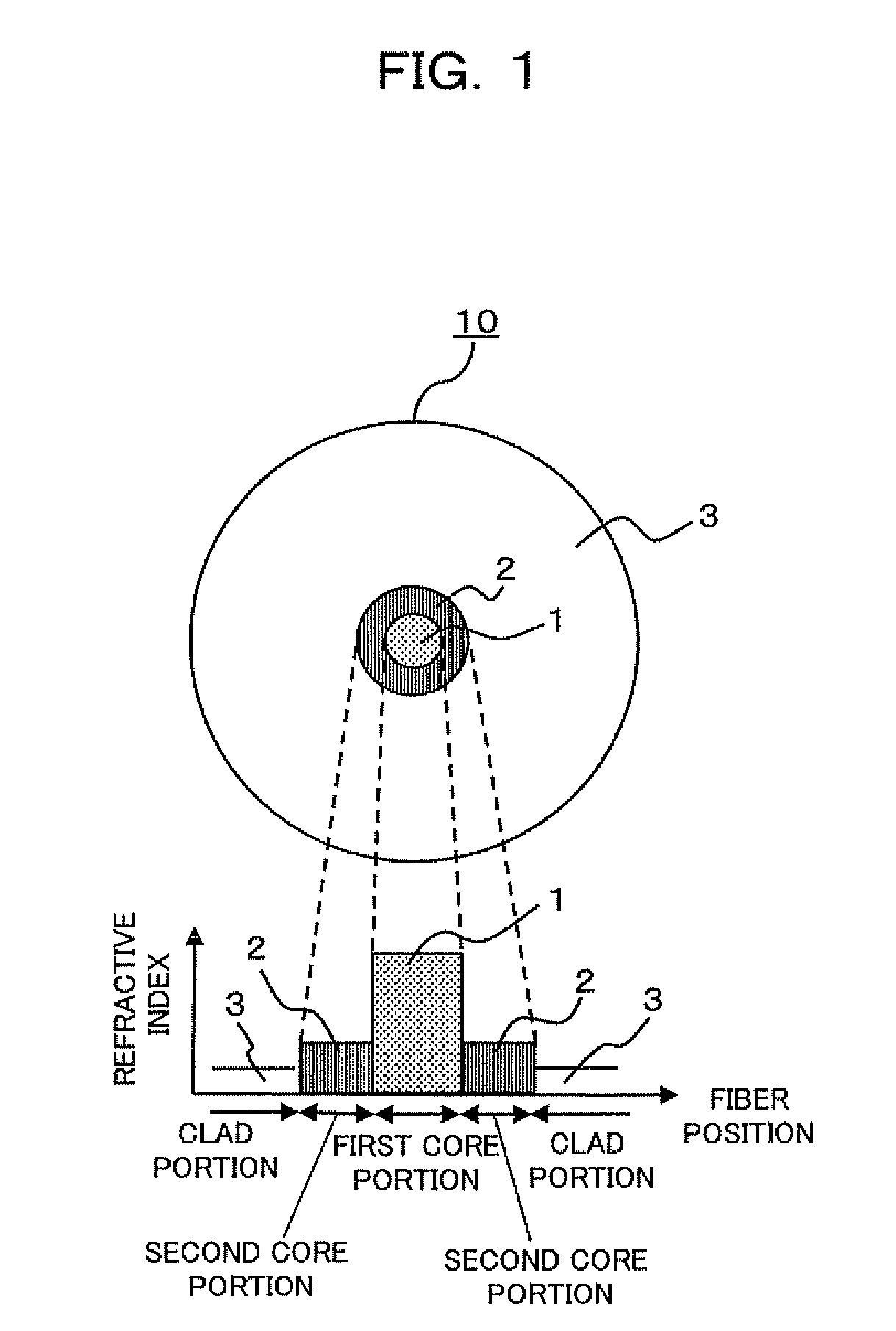
[0093]FIG. 1 is a diagram showing a cross sectional structure of a rare earth ion doped optical fiber and a distribution of refractive index according to one embodiment of the present invention. As shown in FIG. 1, a rare earth ion doped optical fiber 10 according to the present embodiment includes, a first core portion 1, a second core portion 2 disposed on an outer circumference of the first core portion 1, and a clad portion 3 disposed on an outer circumference of the second core portion 2.

[0094] Further, the rare earth ion doped optical fiber 10 is configured so that the first core portion 1 has a greater refractive index than refractive indexes of the second core portion 2 and the clad portion 3, the refractive index of the second core portion 2 is smaller than that of the first core portion 1 but greater than that of the clad portion 3, and the refractive index of the clad portion 3 is smaller than the refractive indexes of the first core portio...


PUM

PropertyMeasurementUnit
wavelengthsaaaaaaaaaa
wavelengthaaaaaaaaaa
refractive indexaaaaaaaaaa

Abstract

An optical fiber includes: a first core portion doped with rare earth ions; a second core portion having a lower refractive index than that of the first core portion, provided along an outer circumference of the first core portion, and doped with the rare earth ions; and a clad portion having a lower refractive index than that of the second core portion and provided along an outer circumference of the second core portion, and is configured such that a concentration of the rare earth ions added to the second core portion is higher than that to the first core portion. With this configuration, it is possible to suppress an amount of FWM crosstalk in an optical amplification by decreasing the length of a fiber while alleviating efficiency deterioration due to concentration quenching.

Description

BACKGROUND OF THE INVENTION [0001] 1) Field of the Invention [0002] The present invention relates to an optical fiber, a manufacturing method of the same, and an optical amplifier, and in particular, to a technique suitable to be used in a Wavelength Division Multiplex transmission system in which a wavelength interval between signals is decreased in comparison with a conventional technique in order to obtain a larger transmission capacity. [0003] 2) Description of the Related Art [0004] A Wavelength Division Multiplex (WDM) transmission system, in which signal light having different wavelengths is transmitted through a single optical fiber, has been put into practical use as means to realize a larger transmission capacity in an optical communications system. Examples of key devices of the WDM transmission system include an optical amplifier that compensates an optical loss at the fiber, and as an example of optical amplifiers that can handle signal light in a C band (1529-1563 nm),...

Claims


Application Information

Patent Timeline
Patent Type & Authority Applications(United States)
IPC IPC(8): G02B6/02
CPCC03B37/01248C03B37/01433C03B37/01838C03B2201/34H01S3/094003G02B6/03633H01S3/06708H01S3/06729C03B2203/29
Inventor NISHIHARA, MASATOHAYASHI, ETSUKOINAGAKI, SHINYA
Owner FUJITSU LTD
Learn More