Eureka AIR delivers breakthrough ideas for toughest innovation challenges, trusted by R&D personnel around the world.

Voltage generator and power supply circuit

Inactive Publication Date: 2008-01-17
ROHM CO LTD
View PDF2 Cites 4 Cited by
  • Summary
  • Abstract
  • Description
  • Claims
  • Application Information

AI Technical Summary

Benefits of technology

[0013] The present invention has been made to overcome the foregoing problems. It is an object of the present invention to provide a voltage generator capable of accurately detecting an anomaly in a reference voltage, and to provide a power supply circuit including the same.
[0020] According to the present invention, the reference voltage determination circuit determines the reference voltage in accordance with the detection current outputted by the reference voltage generator. Thus, the circuit of the present invention can reliably detect or predetect an anomaly in the reference voltage, as compared to a case in which the reference voltage is determined by using a comparator or the like. Moreover, the circuit of the present invention can suppress an increase in power consumption because of using an over current, which has not heretofore been used, for detection of the anomaly in the reference voltage.

Problems solved by technology

This causes a drop in the output voltage, resulting in the problem of causing malfunctioning of electronics or the like connected to the power supply circuit.
However, even if generated separately, the second reference voltage likewise undergoes variations due to abnormal battery conditions or the like.
Even with the use of the second reference voltage for comparison with the first reference voltage, therefore, the comparator cannot accurately detect an anomaly in the first reference voltage.

Method used


Image

  • Voltage generator and power supply circuit
  • Voltage generator and power supply circuit
  • Voltage generator and power supply circuit

Examples


Embodiment Construction

[0024] Various embodiments of the present invention will be described with reference to the accompanying drawings. It is to be noted that the same or similar reference numerals are applied to the same or similar parts and elements throughout the drawings, and description of the same or similar parts and elements will be omitted or simplified. In the following descriptions, numerous specific details are set forth such as specific signal values, etc. to provide a thorough understanding of the present invention. However, it will be obvious to those skilled in the art that the present invention may be practiced without such specific details. In other instances, well-known circuits have been shown in block diagram form in order not to obscure the present invention with unnecessary detail.

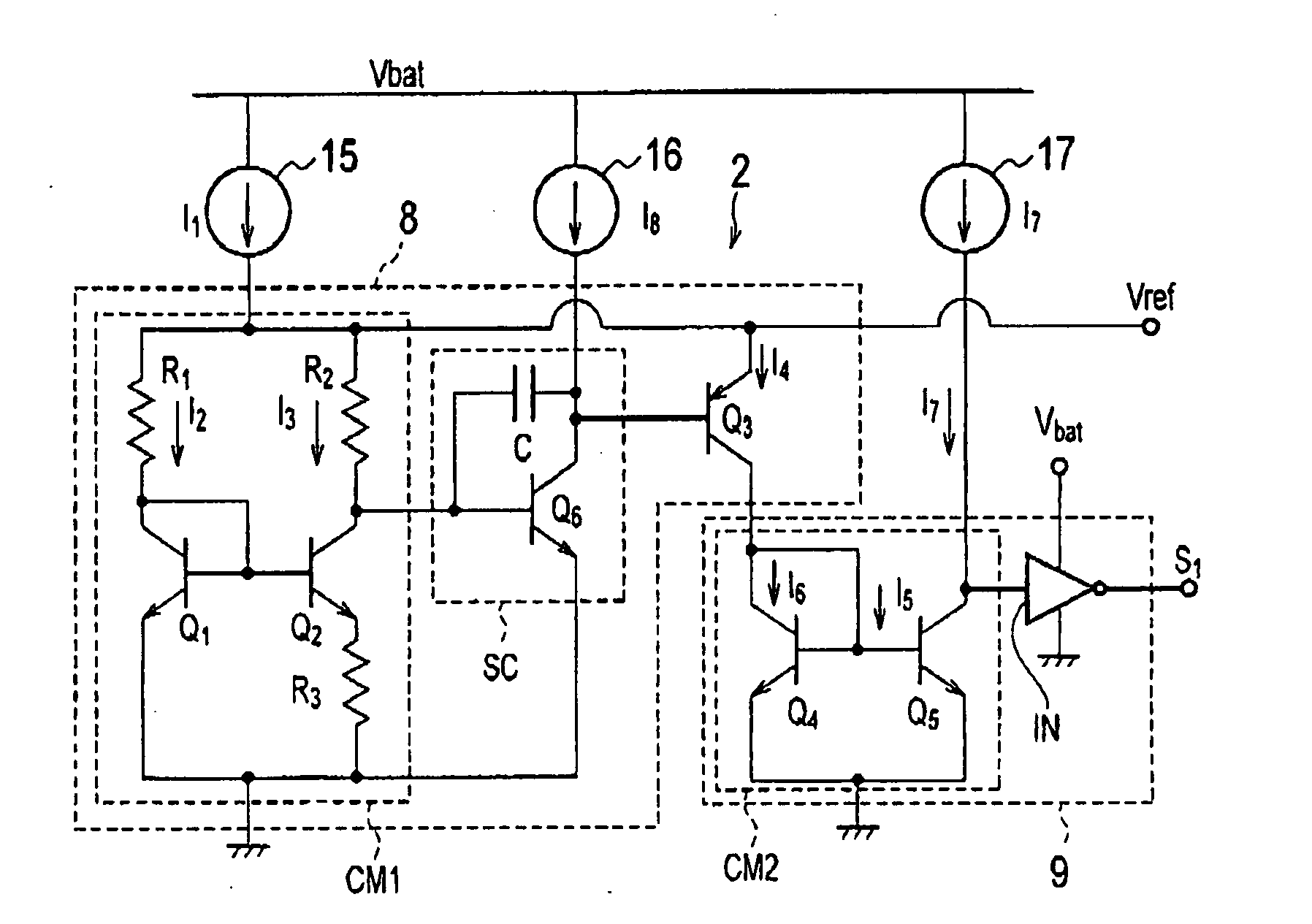
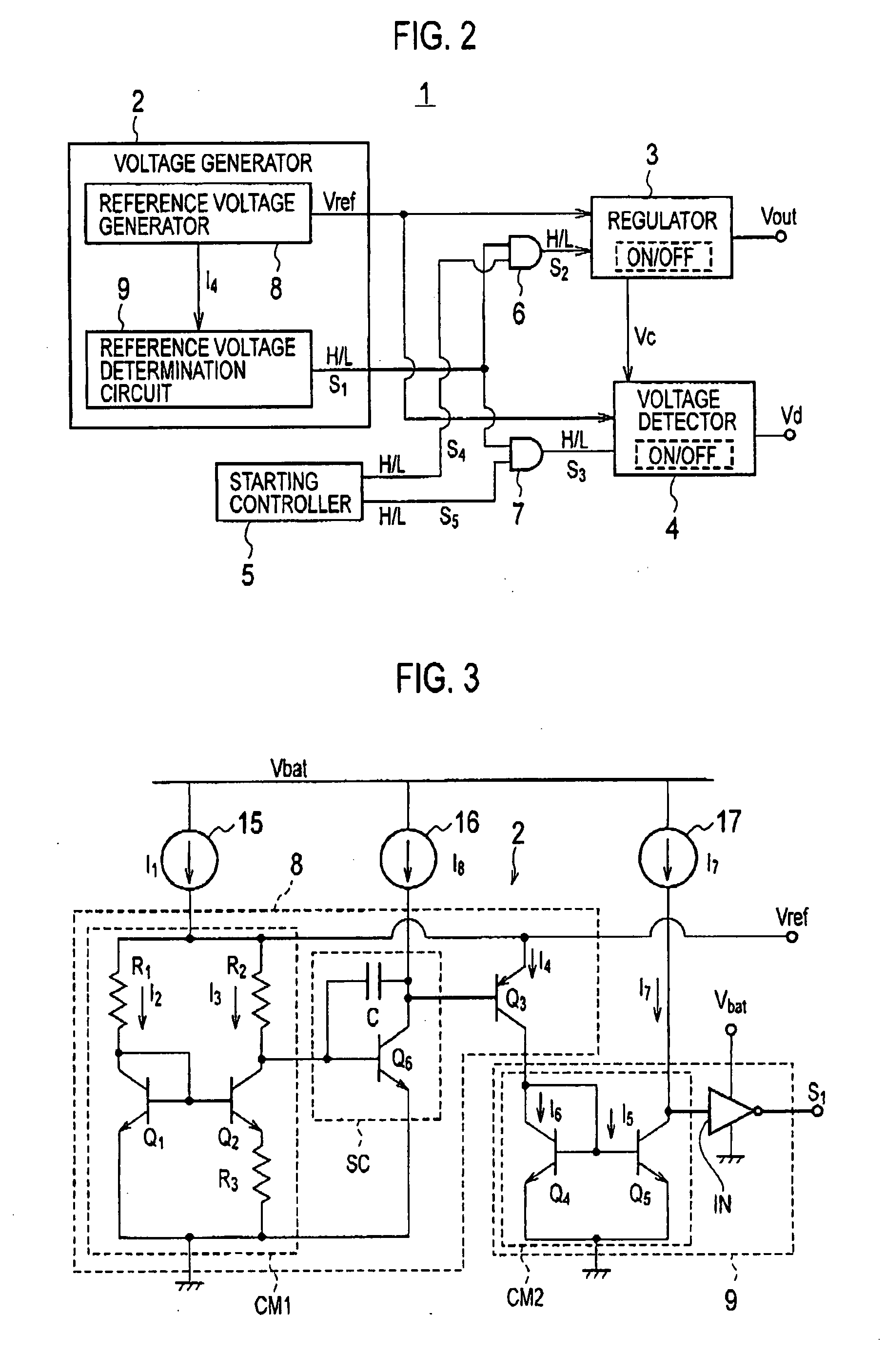
[0025]FIG. 2 is a diagram showing the general configuration of a power supply circuit according to an embodiment of the present invention. FIG. 3 is a circuit diagram of a voltage generator according to...


PUM


Abstract

A voltage generator according to the present invention includes a reference voltage generator and a reference voltage determination circuit. The reference voltage generator outputs a detection current when generating a predetermined reference voltage by a passage of an electric current having a predetermined current value or higher. The reference voltage determination circuit detects or predetects an anomaly in the reference voltage in accordance with the detection current outputted by the reference voltage generator, and then outputs a determination signal.

Description

CROSS REFERENCE TO RELATED APPLICATION [0001] This application is based upon and claims the benefit of priority from prior Japanese Patent Application P2006-167824 filed on Jun. 16, 2006; the entire contents of which are incorporated by reference herein. BACKGROUND OF THE INVENTION [0002] 1. Field of the Invention [0003] The present invention relates to a voltage generator for generating a reference voltage and a power supply circuit including the voltage generator. [0004] 2. Description of the Related Art [0005] A reference voltage generator (or a voltage generator) for inputting a reference voltage to a regulator or the like for outputting a constant voltage, and a power supply circuit including the voltage generator has been known. [0006] Japanese Patent Publication No. H7-281769, for example, discloses a power supply circuit including a reference voltage generator, a voltage comparator, a voltage detector and a switching circuit. In the power supply circuit, the reference voltag...

Claims


Application Information

Patent Timeline
IPC IPC(8): G05F1/618
CPCG05F3/30
Inventor SASAKI, YOSHIKAZUYAMAMOTO, ISAO
Owner ROHM CO LTD
Why Eureka
Eureka Blog
Learn More