
Pilot reference transmission for a wireless communication system

a wireless communication system and pilot reference technology, applied in the field of data communication, can solve the problems of affecting the quality of the received pilot reference, affecting the quality of the transmission received at the remote terminal, and worse interference, so as to minimize the amount of interference, and maximize the amount of interference

Inactive Publication Date: 2008-01-10
QUALCOMM INC
View PDF103 Cites 19 Cited by
  • Summary
  • Abstract
  • Description
  • Claims
  • Application Information

AI Technical Summary

Benefits of technology

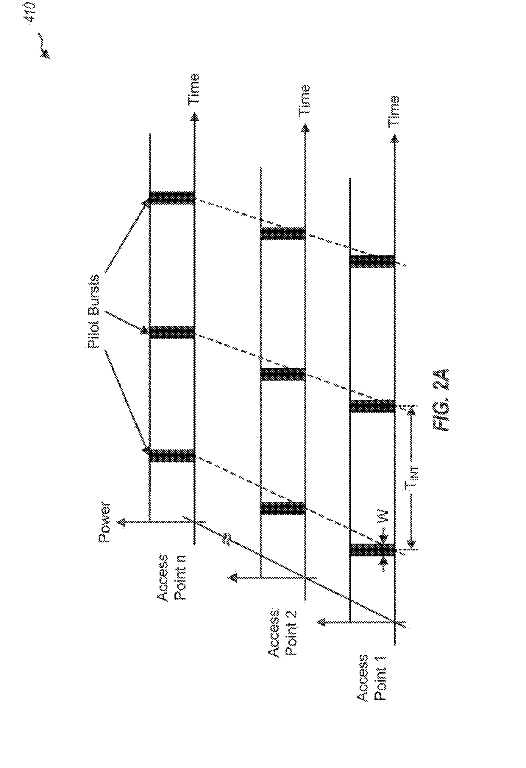
The present invention provides a better pilot reference transmission scheme for high data rate wireless communication systems. It involves transmitting pilot references in bursts at predetermined time intervals, synchronized with the system time reference. This results in maximum interference from neighboring transmission sources and minimizes interference from non-transmitting sources during data transmission. The pilot bursts are received at the access terminals only in the presence of pilots from other access points, without being affected by other data transmissions. This results in a signal-to-noise ratio for the pilot reference that represents the minimum signal-to-noise ratio during data transmission from the given access point, aiding in rapid and reliable estimation of worst case carrier-to-interference (C / I). The method includes receiving signals indicative of a time reference and generating pilot bursts for a pilot reference in a synchronized manner. The pilot bursts can be transmitted at or near the maximum transmit power level and in the absence of any data transmission. Overall, this pilot reference transmission scheme improves the reliability and accuracy of wireless communication systems.

Problems solved by technology

This interference degrades the quality of the transmissions received at a remote terminal, including the pilot transmission.
The interference from these other transmissions can affect the quality of the received pilot reference.
This interference is worse when the orthogonality between the pilot channel and the traffic channels used for the data transmissions is lost due to, for example, multipath.
However, for a high-speed data transmission system in which the link condition is required to be accurately estimated within a short period of time, this continuous low-level pilot reference is not adequate.

Method used


Image

  • Pilot reference transmission for a wireless communication system
  • Pilot reference transmission for a wireless communication system
  • Pilot reference transmission for a wireless communication system

Examples


Embodiment Construction

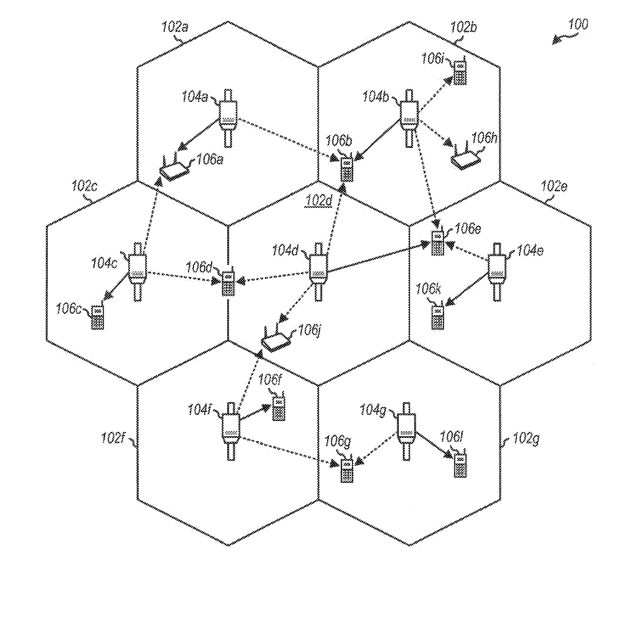
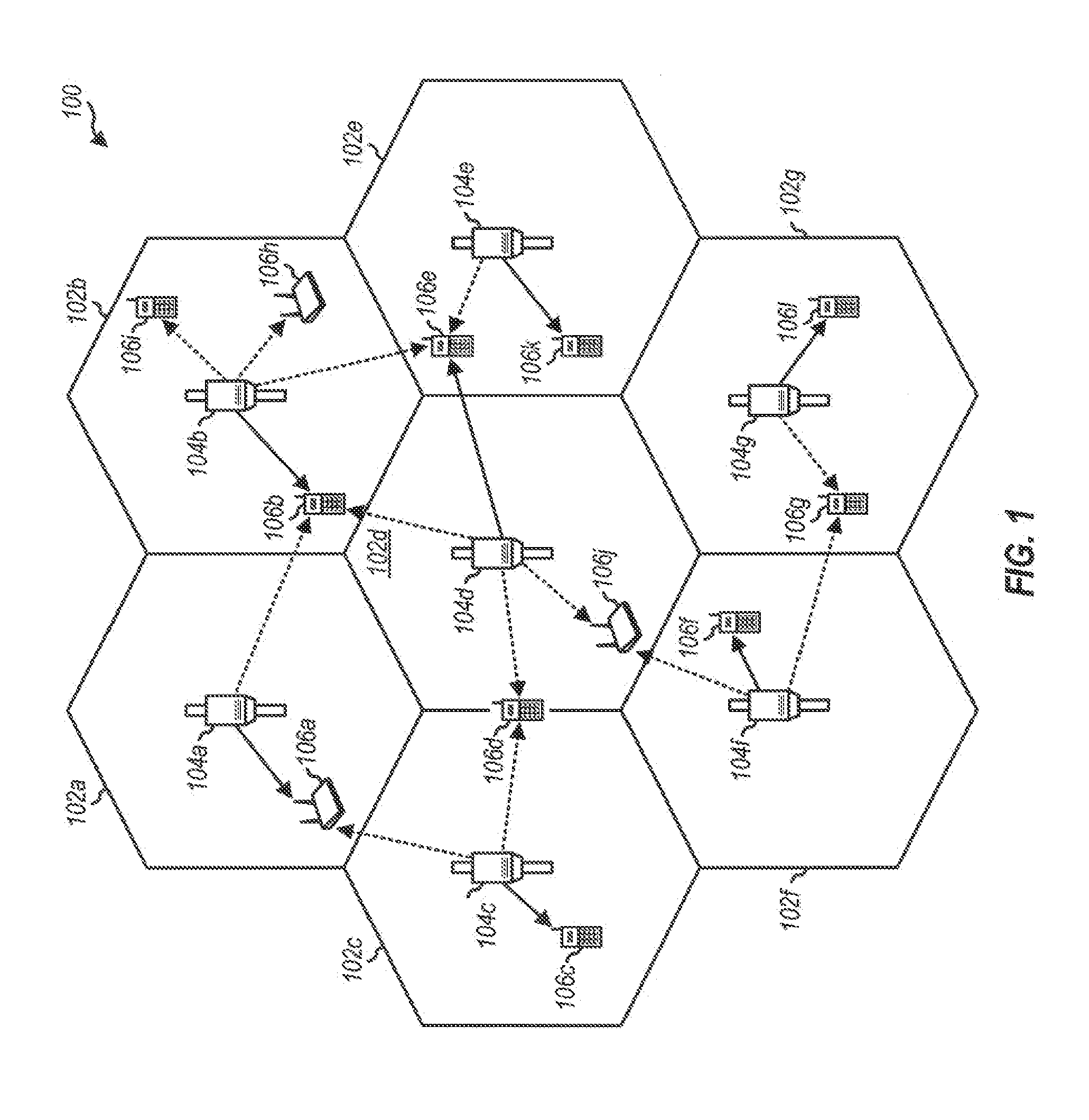
[0023]FIG. 1 is a diagram of a wireless communication system 100 that supports a number of users and transmits pilot references. System 100 provides communication for a number of cells 102a through 102g, with each cell 102 being serviced by a corresponding access point 104 (which may also be referred to as a base station). Various access terminals 106 (which may also be referred to as remote terminals or mobile stations) are dispersed throughout the system.

[0024] In an embodiment, each access terminal 106 may communicate with one access point 104 on the forward link at any given moment, and may communicate with one or more access points on the reverse link depending on whether the access terminal is in soft handoff. The forward link (i.e., downlink) refers to transmission from the access point to the access terminal, and the reverse link (i.e., uplink) refers to transmission from the access terminal to the access point. System 100 may be designed to conform to a particular CDMA sta...


PUM


Abstract

A pilot reference transmission scheme well suited for high data rate wireless communication systems is disclosed. To maximize the amount of interference from transmissions from neighboring transmission sources (e.g., access points or base stations) during the pilot interval, and hence minimize the amount of interference from non-transmitting sources during the data intervals, the pilot references are transmitted in bursts at predetermined time intervals, and the pilot bursts from the access points are synchronized. This results in maximum interference contributions from non-transmitting neighboring access points, facilitating reliable estimation of worst case carrier-to-interference (C / I), and further allows the receiving devices (e.g., access terminals) to easily recognize the bursts as pilot reference. In one embodiment, each access point transmits the pilot bursts at or near its maximum transmit power level and no user-specific data is transmitted during the pilot bursts.

Description

CROSS REFERENCE TO RELATED APPLICATIONS [0001] The present application is a Continuation of U.S. patent application Ser. No. 09 / 702,142, entitled “PILOT REFERENCE TRANSMISSION FOR A WIRELESS COMMUNICATION SYSTEM”, filed Oct. 30, 2000, which is a Continuation-in-Part of U.S. patent application Ser. No. 09 / 575,073, entitled “HIGH DATA RATE WIRELESS PACKET DATA COMMUNICATIONS SYSTEM,” filed May 19, 2000, now U.S. Pat. No. 6,894,994, which is a Continuation-in-Part of U.S. patent application Ser. No. 08 / 963,386, entitled “METHOD AND APPARATUS FOR HIGH RATE PACKET DATA TRANSMISSION,” filed Nov. 3, 1997, now U.S. Pat. No. 6,574,211, which claims the benefit of provisional U.S. Application Ser. No. 60 / 163,350, entitled “HIGH DATA RATE SYSTEM AND TECHNOLOGY,” filed Nov. 3, 1999, all of which are assigned to the assignee of the invention and incorporated herein by reference.BACKGROUND OF THE INVENTION [0002] I. Field of the Invention [0003] The present invention relates to data communication...

Claims


Application Information

Patent Timeline
Patent Type & Authority Applications(United States)
IPC IPC(8): H04J3/00
CPCH04B1/707H04B7/2687H04W52/325H04J3/0644H04B2201/70701
Inventor PADOVANI, ROBERTOBLACK, PETER J.SINDHUSHAYANA, NAGABHUSHANA T.
Owner QUALCOMM INC
Learn More