
Elongated member/radially expandable member assembly and methods of assembling the same

a technology of radial expansion and elongation member, which is applied in the direction of mechanical equipment, manufacturing tools, couplings, etc., can solve the problems of difficult for the installer to properly and/or accurately index and/or and the union between the components is less than satisfactory, and the elongated member is difficult to properly and/or accurately orient the elongated member

Inactive Publication Date: 2008-01-10
FATIGUE TECH
View PDF25 Cites 51 Cited by
  • Summary
  • Abstract
  • Description
  • Claims
  • Application Information

AI Technical Summary

Benefits of technology

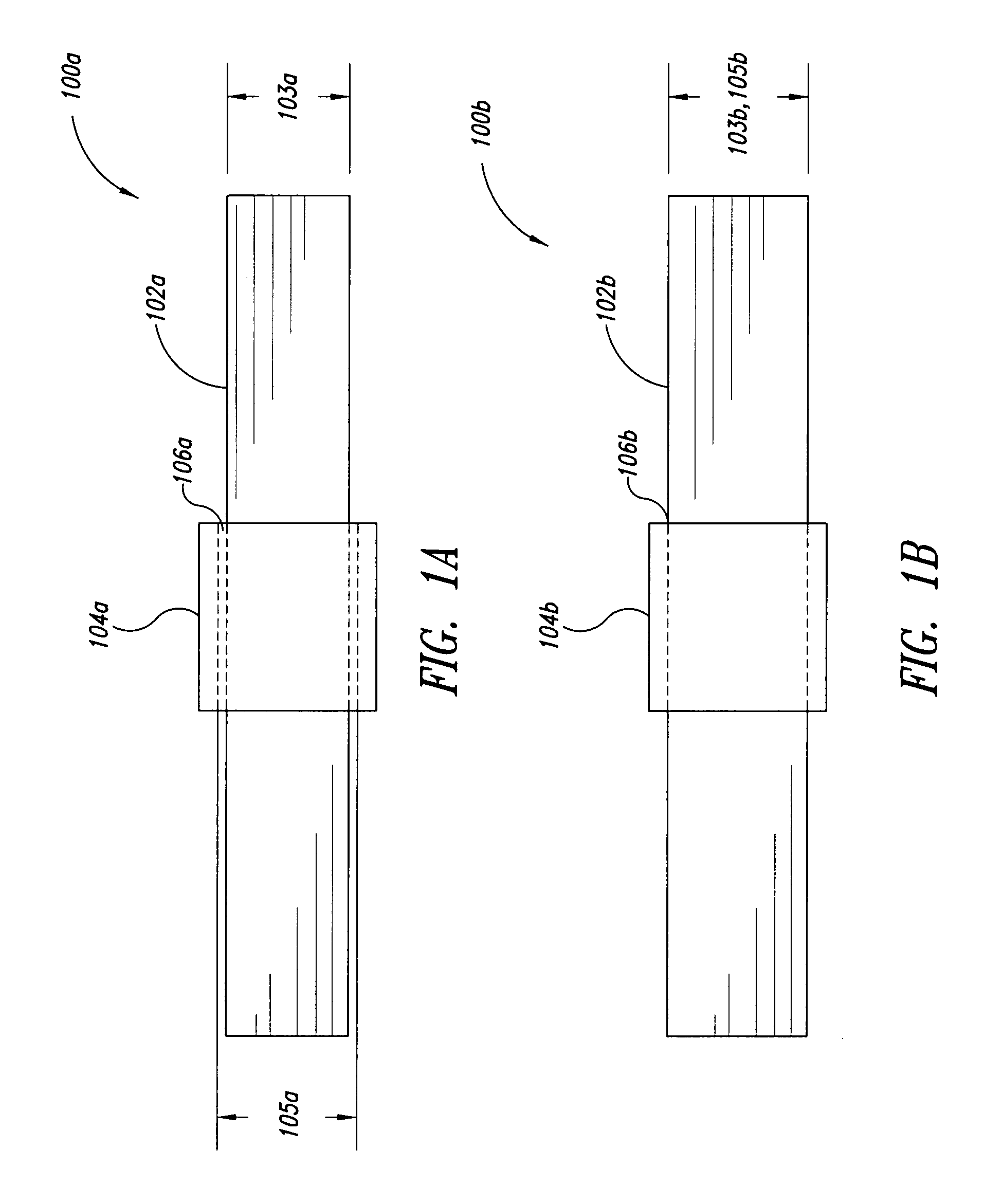
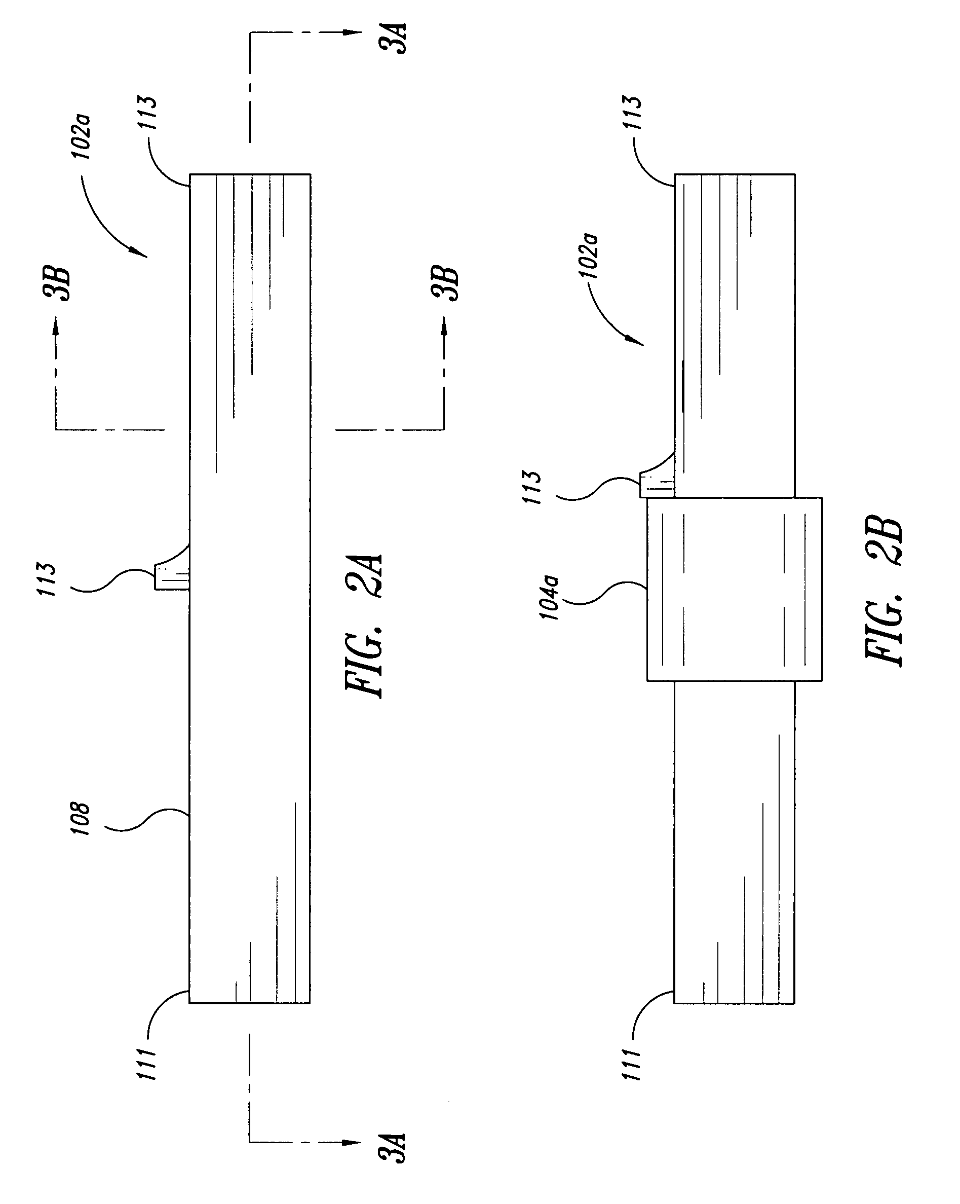
The patent text describes a method for installing a radially expandable member onto an elongated member using cold-working / radial-expansion techniques. The method involves using an installation tool to draw an elongated expansion mandrel through the elongated member and locally, radially expand at least a portion of the elongated member to create an interference fit with the radially expandable member. The elongated member and the radially expandable member can be assembled using press fit techniques, shrink fit techniques, clearance fit techniques, or other methods. The assembled components can be used in a load path assembly or an assembly for transmitting loads. The technical effects of the patent text include improved installation of radially expandable members onto elongated members and improved load path assembly.

Problems solved by technology

One drawback of the shrink fit assembly technique is that the elongated member must be placed in the radially expandable member, or vice-versa, quite rapidly because the dimensions of the elongated member will immediately and rapidly begin to increase once the elongated member is removed from the cryogenic fluid.
The limited time available for an installer to assemble the components means that it is often difficult for the installer to properly and / or accurately index and / or orient the elongated member relative to the radially expandable member, if and when such indexation or orientation is necessary.
In press fitting processes, the tolerances between the radially expandable member and elongated member must be held very close; otherwise, the components may interfere too much and may not fit together or, in contrast, interfere too little, resulting in a less than satisfactory union between the components.
In addition, press fitting is typically limited to use on smaller assemblies; otherwise, the pressing forces exceed the capabilities of even large mechanical presses.
The press fitting process may be limited by the types of materials forming the components being assembled, may require large capital costs for specialized tooling to assemble uniquely shaped parts by applying large, controlled forces, and / or may cause unwanted damage to the components, in particular the surfaces that are in sliding, frictional contact during the press fit operation.
These drawbacks, and others, may lead to manufacturing difficulties, increased manufacturing costs, in-service problems, and / or degraded operational performance of the components that were shrunk and / or press fit together.
The process may provide numerous benefits over shrink and / or press fitting, such as possibly increasing the fatigue life of components that will undergo repetitive load cycles and / or may be susceptible to accumulating fatigue damage during service.

Method used


Image

  • Elongated member/radially expandable member assembly and methods of assembling the same
  • Elongated member/radially expandable member assembly and methods of assembling the same
  • Elongated member/radially expandable member assembly and methods of assembling the same

Examples


Embodiment Construction

[0043] In the following description, certain specific details are set forth in order to provide a thorough understanding of various embodiments of the invention. However, one skilled in the art will understand that the invention may be practiced without these details. In other instances, well-known structures and methods associated with cold working and / or passing a mandrel through a component to produce some amount of radial expansion of the component may not be shown or described in detail to avoid unnecessarily obscuring descriptions of the embodiments of the invention. It is appreciated and understood that the process of cold working and / or radial expansion may or may not result in the creation of improved fatigue life, which may provide improved characteristics for resisting crack formation, initiation, and / or propagation during operational, thermal, and / or other loading scenarios.

[0044] In the following description and for purposes of brevity, reference shall be made to the p...


PUM

PropertyMeasurementUnit
axial lengthaaaaaaaaaa
lengthaaaaaaaaaa
inner perimeteraaaaaaaaaa

Abstract

At least one embodiment generally relates to using an installation tool to pass an expansion mandrel through an elongated member to at least locally, radially expand at least a portion of the elongated member and achieve an interference fit with a radially expandable member located about an outer surface of the elongated member. In one embodiment, the elongated member is radially expanded over its entire length and may include a stepped feature so that only a portion of the elongated member achieves the interference fit with the radially expandable member. During the radial-expansion process, both the radially expandable member and the elongated member may be at the same or approximately the same temperature. Before the radial-expansion process, the radially expandable member may be assembled using press-fit techniques, shrink fit techniques, clearance fitting techniques, or combinations thereof.

Description

CROSS-REFERENCE TO RELATED APPLICATION [0001] This application claims the benefit under 35 U.S.C. § 119(e) of U.S. Provisional Patent Application No. 60 / 808,600, filed May 26, 2006, where this provisional application is incorporated herein by reference in its entirety.BACKGROUND OF THE INVENTION [0002] 1. Field of the Invention [0003] This disclosure generally relates to methods of installing radially expandable members onto hollow, elongated members such as elongated members, axles, and / or shafts. [0004] 2. Description of the Related Art [0005] One conventional process for installing radially expandable members on elongated members such as elongated members, axles, and / or shafts is a thermal technique where the radially expandable member, the elongated member, or both are respectively heated and / or cooled. When cooling is used, the process is generally referred to as a shrink or a freeze fit process. In one example, the receiving part would be the radially expandable member and the...

Claims


Application Information

Patent Timeline
Patent Type & Authority Applications(United States)
IPC IPC(8): B23P9/00
CPCB21C3/16B21C37/154B21D53/845B21K25/00B23P9/025Y10T29/49945B23P11/005B23P2700/02F16D1/072F16D2250/00Y10T29/4994B23P11/00
Inventor GLENN, DOUGLAS W.KOKALY, MATTHEW T.MADDEN, DEAN C.
Owner FATIGUE TECH
Learn More