Surgical instrument with detachable tool assembly
a surgical instrument and tool assembly technology, applied in the field of surgical instruments with detachable tool assemblies, can solve the problems of requiring two-handed rotation of components and clumsy disconnection of tools from shafts, and achieve the effect of preventing potential contamination
- Summary
- Abstract
- Description
- Claims
- Application Information
AI Technical Summary
Benefits of technology
Problems solved by technology
Method used
Image


Examples
first embodiment
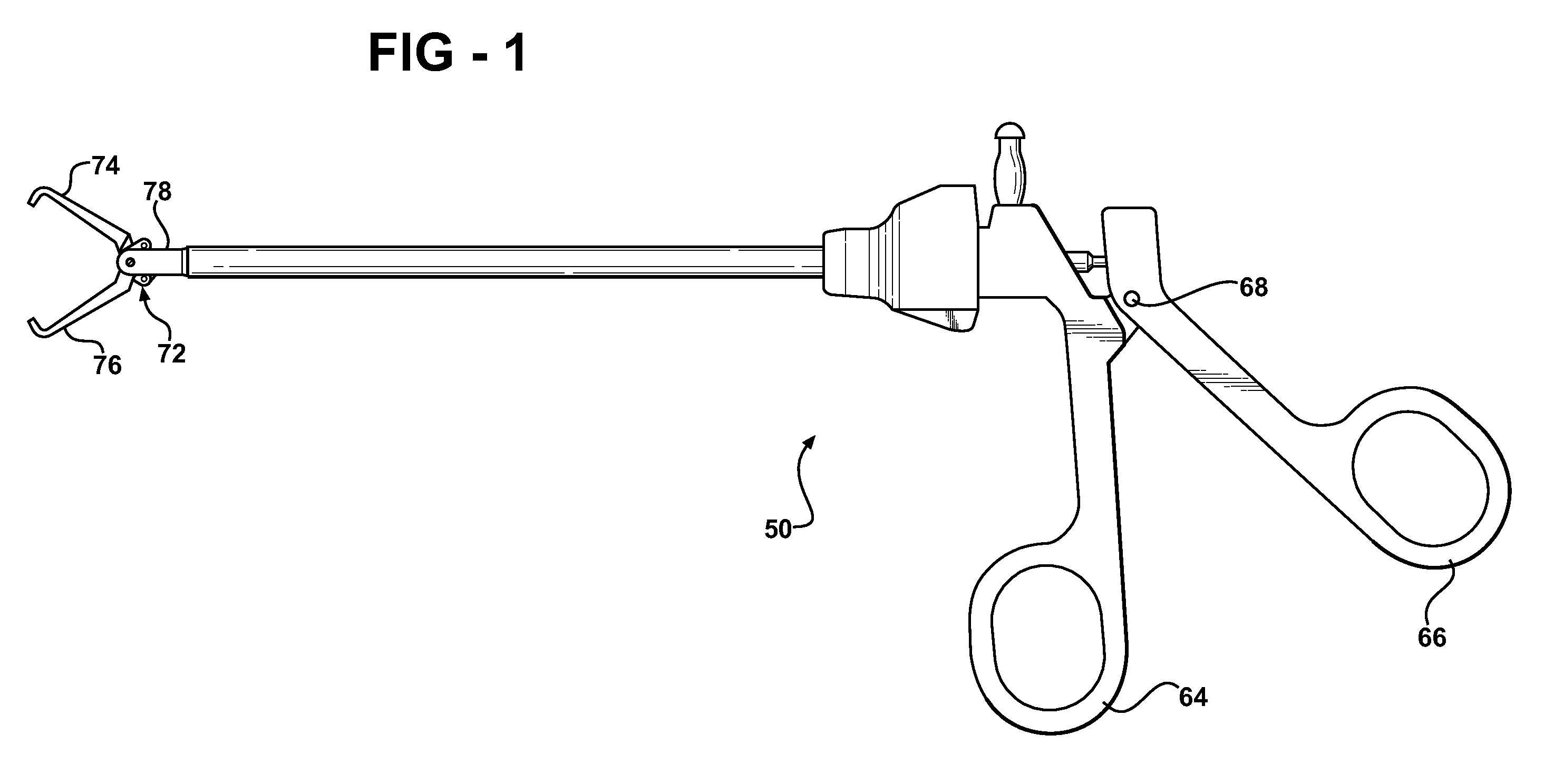
[0057] In a first embodiment, as shown in FIG. 1, the surgical instrument 50 is forceps primarily for use in performing endoscopic or arthroscopic surgery, specifically for the grasping of objects during such surgery. The components of the surgical instrument 50 are typically formed of a metal, such as a stainless steel. However, the various components of the surgical instrument may be formed of other materials as are known to those skilled in the art.
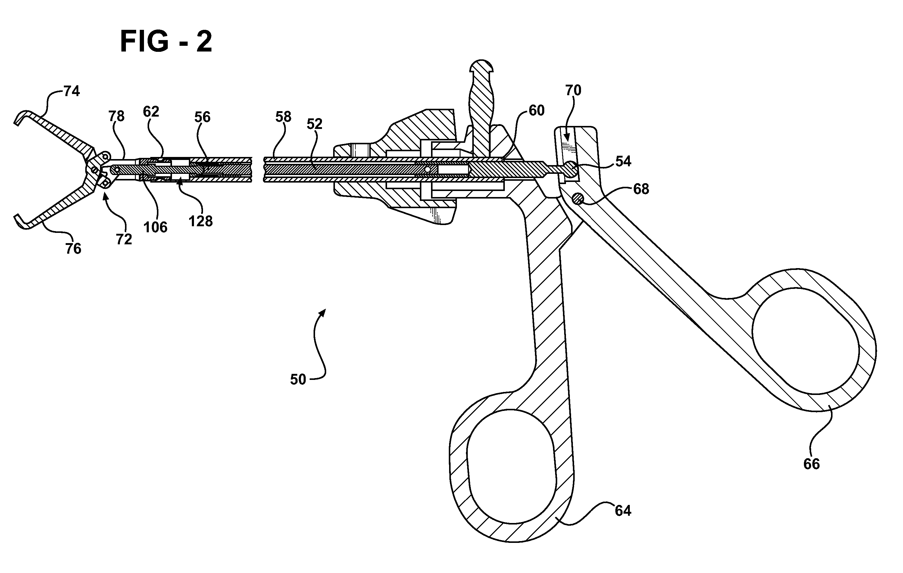
[0058] Referring now to FIG. 2, the surgical instrument 50 includes a shaft 52 having a proximal end 54 and a distal end 56. Preferably, the shaft 52 is rod-shaped with a generally circular cross section. However, the cross section of the shaft 52 may define other shapes. For instance, the cross section of the shaft 52 may be square or triangular (both not shown).
[0059] The shaft 52 is disposed at least partially in a housing 58. That is, the housing 58 surrounds at least a portion of the shaft 52. The housing 58 is preferably tubular...
second embodiment
[0078] In the second embodiment, a pin assembly 152 pivotally connects the jaws 74, 76 via the pivot holes 88. The pin assembly 152 includes a pair of expanded heads 154 interconnected by a pin 156. The pin assembly 152, and specifically the expanded heads 154, extends beyond the jaws 74, 76 on both sides of the jaws 74, 76. To couple the assembly 72 with the housing 58, the pin assembly 152 is slid through the inlet slots 149 and into the clevis holes 86. The expanded heads 154 snap lock with the clevis component 78 in the clevis holes 86. The connection rod 106 carries a perpendicular extension 158. The perpendicular extension 158 mates with the slot 84 of the clevis component 78 which force correct alignment of the assembly 72 and particularly the expandable heads 154 to the clevis holes 86.
[0079]FIGS. 35-41 show a third embodiment of the invention. In the third embodiment the detachable tool assembly 72 is implemented as an electrode 158 for applying electrical current to tissue...
fourth embodiment
[0080] The electrode 158 includes a proximal end 160 and a distal end 162. In the fourth embodiment, as illustrated, the distal end 162 is ball shaped to provide a round surface for application of electrical energy. However, those skilled in the art realize other shapes for the distal end 162, such as, but not limited to, a needle tip or a scalpel shape.
[0081] The electrode 158 forms a void 163 extending inward from the proximal end 160. The electrode 158 includes a connection rod 164 that extends through the void and outward past the proximal end 160. The connection rod 164 includes a ball-shaped end 166. The ball-shaped end mates with the collet 116 such that the electrode 158 may be secured in place or ejected by the fingers 120 of the collet 116.
[0082] The proximal end 160 of the electrode 158 is detachably connected to the distal end 62 of the housing 58 in a similar fashion to the collet component 78 and housing 58 in the first embodiment. In a first configuration, as shown i...
PUM
 Abstract
Description
Claims
Application Information
 - R&D
- Intellectual Property
- Life Sciences
- Materials
- Tech Scout
- Unparalleled Data Quality
- Higher Quality Content
- 60% Fewer Hallucinations
Browse by: Latest US Patents, China's latest patents, Technical Efficacy Thesaurus, Application Domain, Technology Topic, Popular Technical Reports.
© 2025 PatSnap. All rights reserved.Legal|Privacy policy|Modern Slavery Act Transparency Statement|Sitemap|About US| Contact US: help@patsnap.com