Wide angle scanner for panoramic display

a wide angle, scanner technology, applied in the field of wide angle scanners, can solve the problems of increasing difficulty, inability to completely hide the seams between images, and current methods for blending the edges of images from adjacent projectors, and achieve the effect of no seams and good color matching

Inactive Publication Date:
View PDF2 Cites 39 Cited by
  • Summary
  • Abstract
  • Description
  • Claims
  • Application Information

AI Technical Summary

Benefits of technology

[0011] It has been recognized that it would be advantageous to develop a direct view display system that can project a wide field of view from a single projection location that is more nearly optimized for a uniform display, and provides good color matching and no seams.

Problems solved by technology

However, it becomes increasingly difficult with increasing field of view to place projectors in locations that provide uniform illumination and resolution, yet are still hidden from view.
In addition, current methods for blending the edges of images from adjacent projectors are not completely effective at hiding the seams between images, and color matching of adjacent images from multiple projectors is very difficult.
The common result is composite images with noticeable seams and inconsistent coloring from one portion of the image to another.
The geometry shown in FIGS. 14 and 15 creates problems for projectors in general and for panoramic displays with multiple projectors in particular.
However, it is impossible to locate multiple projectors at a single point in space.
Additionally, the low f-number lenses required for CRT projectors normally used do not have sufficient depth of focus to allow positioning at the preferred location 130.
Also, large projectors in these positions are problematic for training applications that use motion bases.
The large mass of multiple projectors placed high above the screen creates an unacceptably large moment of inertia for simulators or other applications incorporating motion systems.
The type of scanner that has been used with laser projectors in the past is not capable of the wide angle, tilted scan required for both a wide angle virtual display and a panoramic real image display.
Since such systems require dynamic synchronization of two elements rotating at different rates while maintaining precise optical alignment through multiple reflections, they are expensive to produce, suffer from accuracy problems, and are heavy and difficult to balance.
Consequently, they are seldom used for high speed scanning systems.
This type of projector is limited in image size vs. projection distance, and therefore creates a narrow image.
This method is unsuitable for a panoramic display because it magnifies the pixels in both the horizontal and vertical directions.
Additionally, bandwidth limitations have hindered the development of a high resolution panoramic display from a single projector modulating a single laser beam.
Unfortunately, mere use of a GLV does not address the problem of creating a panoramic display on a curved screen.

Method used


Image

  • Wide angle scanner for panoramic display
  • Wide angle scanner for panoramic display
  • Wide angle scanner for panoramic display

Examples


Embodiment Construction

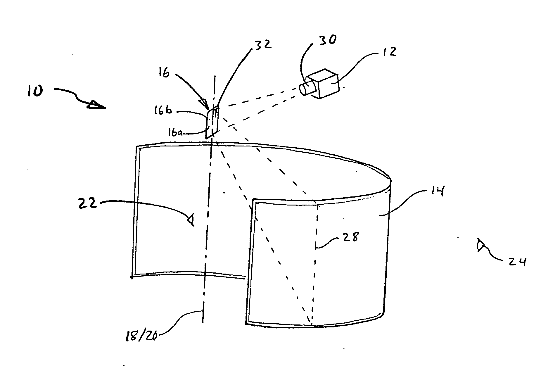
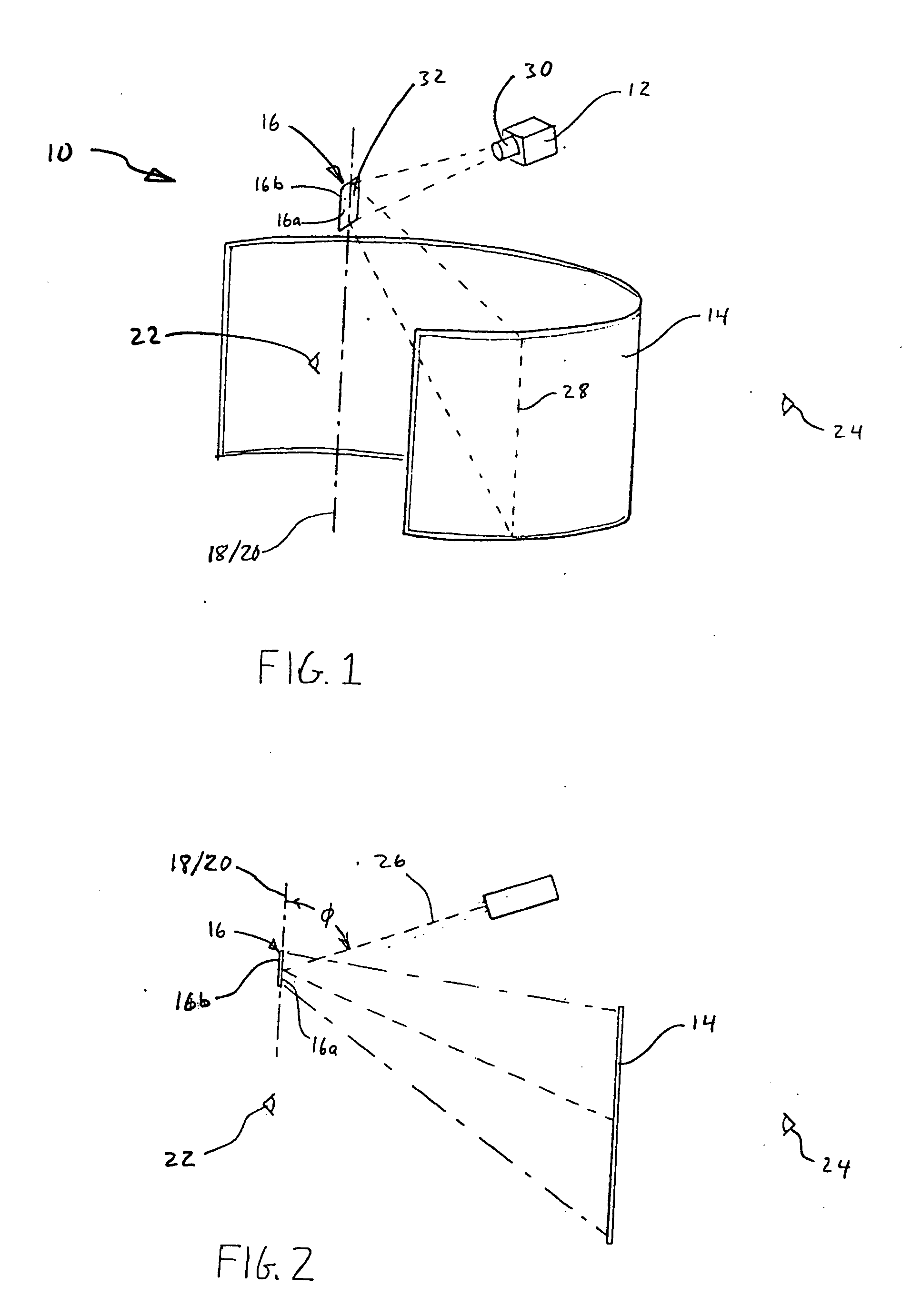
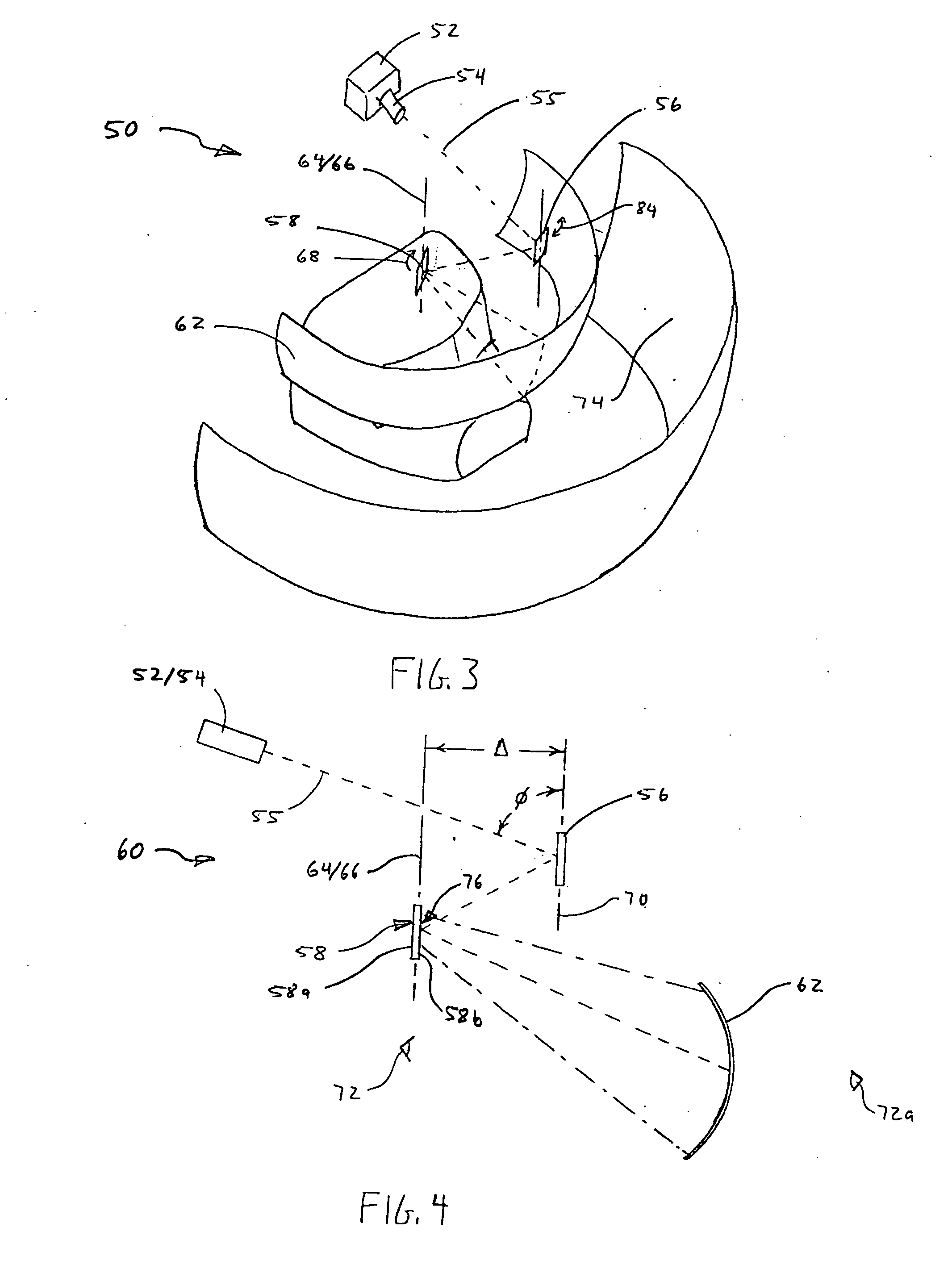
[0040] The following detailed description of exemplary embodiments of the invention makes reference to the accompanying drawings, which form a part hereof and in which are shown, by way of illustration, exemplary embodiments in which the invention may be practiced. While these exemplary embodiments are described in sufficient detail to enable those skilled in the art to practice the invention, it should be understood that other embodiments may be realized and that various changes to the invention may be made without departing from the spirit and scope of the present invention. Thus, the following more detailed description of the embodiments of the present invention, as represented in FIGS. 1 through 20, is not intended to limit the scope of the invention, as claimed, but is presented for purposes of illustration only and not limitation to describe the features and characteristics of the present invention, to set forth the best mode of operation of the invention, and to sufficiently ...


PUM


Abstract

A wide angle display system includes a linear array projector, a curved display surface, and an n-sides scanning mirror. The projector is configured to project an image along an optical axis to the scanning mirror. The scanning mirror continuously rotates about a rotational axis at a speed 1/n the refresh rate, so as to reflect and scan the image onto the display surface.

Description

RELATED APPLICATIONS [0001] This application is a continuation-in-part application, which claims priority to copending U.S. patent application Ser. No. 10 / 642,880, filed Aug. 18, 2003, and entitled, “Wide Angle Scanner for Panoramic Display,” which is incorporated by reference in its entirety herein.FIELD OF THE INVENTION [0002] The present invention relates generally to panoramic visual display systems. More particularly, the present invention relates to a system for providing a very wide angle display using a single projector. BACKGROUND OF THE INVENTION AND RELATED ART [0003] A panoramic display is generally considered one in which the horizontal dimension is much greater than the vertical dimension, such that the display horizontally wraps around the viewing point, at least partially. Panoramic visual display systems are desirable in a number of applications. One particular application needing wide fields of view is flight simulation and training. Heretofore, panoramic flight si...

Claims


Application Information

Patent Timeline
Patent Type & Authority Applications(United States)
IPC IPC(8): G03B21/28G03B21/32
CPCG03B21/32G03B21/606G03B37/02H04N9/3129G09B9/32
Inventor STREID, HARRYCHRISTENSEN, ROBERT R.TANNER, ALLEN H.
Why Eureka
Try Eureka