
Slider assembly having a position changing module

Inactive Publication Date: 2007-12-20
NOKIA CORP
View PDF9 Cites 1 Cited by
  • Summary
  • Abstract
  • Description
  • Claims
  • Application Information

AI Technical Summary

Benefits of technology

[0005]In a device having two device parts with one device part arranged to slide against the other, the present invention uses a module, such as a modular spring system, to control the sliding operation. The modular spring system has a module body to accommodate a cam shaft holder on one end and a blocking surface on the other end, along a body axis. The cam shaft holder has a well to accommodate a cam shaft, allowing the cam shaft to rotate therein about a rotational axis. The rotational axis is substantially perpendicular the body axis of the module body. The well has an open section and the cam shaft has a cam tip located near the open section so as to allow a slider with a protruding portion to press against the cam tip through the open section of the well in order to provide a nose interface. A spring is inserted between the blocking surface and the slider to provide stability of a nose interface position. Depending on the shape of the protruding portion of the slider and the shape of the cam tip, the modular spring system can have one, two or more stable nose interface positions. When the cam shaft is rotated so as to move the cam tip from one stable position to another stable position, the slider is caused to temporarily move backward. The cam shaft also has a locking member inserted into a recess or an opening on the cam shaft holder. The locking member prevents the cam shaft from moving out of the well along the rotational axis while allowing the cam shaft to rotate between nose interface positions.

Problems solved by technology

Furthermore, the required distance between the relative positions is quite large.

Method used


Image

  • Slider assembly having a position changing module
  • Slider assembly having a position changing module
  • Slider assembly having a position changing module

Examples


Embodiment Construction

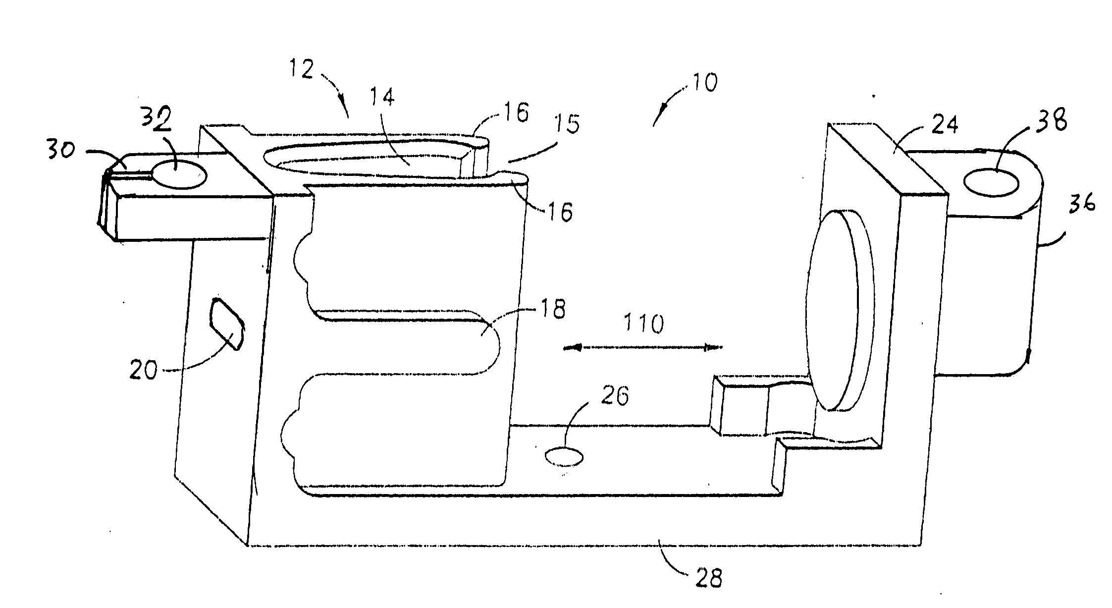
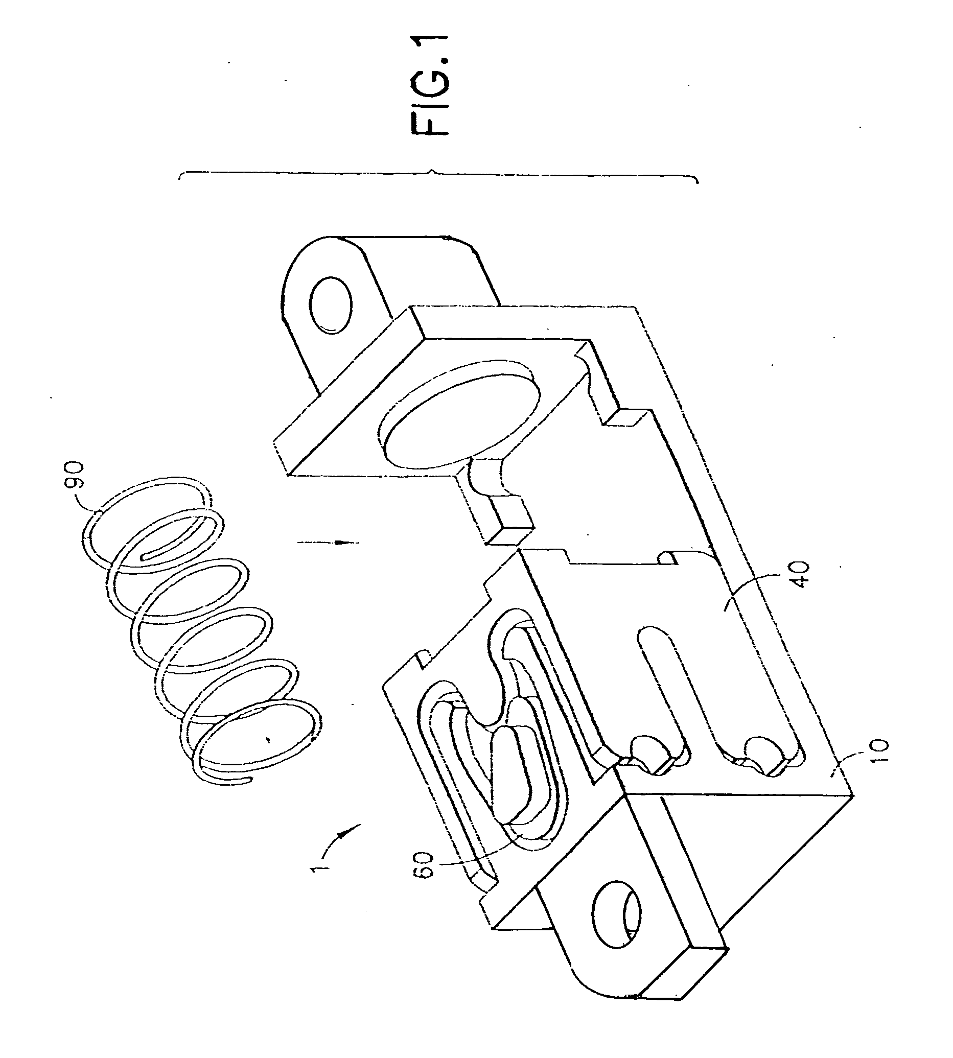
[0048]The modular spring system 1, according to the present invention, has a module body 10 to hold a cam shaft 60 and a module slider 40 to provide nose interfaces between the module slider and the cam shaft, as shown in FIG. 1. A spring 90 is used to urge the module slider to press against the cam shaft along the module body axis 110, as shown in FIG. 2.

[0049]As shown in FIG. 2, the module body 10 has a module base 28, a cam shaft holder 12 located on one end and an end block 24 on the other end. The cam shaft holder 12 has two arms 16 to define a shaft well 14. Each of the arms 16 has an alignment guide 18 to guide the module slider 40 into position in the assembling process. The arms 16 define an opening section 15 of the cam shaft holder 12. The cam shaft holder has a retaining aperture 20 to prevent the cam shaft 60 from sliding off the shaft well 14 along the axis 160 (see FIG. 3) after all the components are assembled. The module base 28 has a mounting hole 26. The module bo...


PUM


Abstract

A sliding assembly has a slider and at least one rail movably engaged with the slider for movement. The rail is coupled to a module operable in a number of module positions. A lever arm is connected between a pin on the slider and the module to change the module positions, such that when the module positions are caused to change, the slider is also caused to move relative to the rail. In a portable device, such as a mobile phone having a first device part and a second device part, the first device part can be fixedly mounted to the slider and the second device part can be fixedly mounted to the rail in order to achieve a sliding motion between the first and second device parts so as to allow the mobile phone to operate between closed and open positions.

Description

[0001]This is a Continuation-In-Part Application of and claiming priority to a pending U.S. patent application Ser. No. 11 / 453,754, filed Jun. 14, 2006, assigned to the assignee of the present invention.FIELD OF THE INVENTION[0002]The present invention relates generally to a slider assembly for use in a hand-held device, such as a mobile phone and, more particularly, to a slider assembly having a nose-to-nose modular system.BACKGROUND OF THE INVENTION[0003]A small portable device, such as a mobile phone, a communicator device and a personal digital assistant, requires a mechanical linkage between two device parts, such as a cover and a device body, so that one device part can be moved to different positions relative to the other device part. It is desirable that the mechanical linkage is small but reliable. Furthermore, when one device part is moved between positions relative to the other device part, the mechanical linkage is stable at least at one of the positions. Furthermore, th...

Claims


Application Information

Patent Timeline
IPC IPC(8): B31B1/88B31B50/88
CPCH04M1/0237
Inventor KARKKOLA, TAPIO
Owner NOKIA CORP
Learn More