
Wireles switching control system for building automation, lighting, security and appliances

Inactive Publication Date: 2007-12-20
NEWICT M
View PDF14 Cites 75 Cited by
  • Summary
  • Abstract
  • Description
  • Claims
  • Application Information

AI Technical Summary

Benefits of technology

[0015] A further object of certain illustrative embodiment of embodiments disclosed herein is to provide a secure yet simple to perform method to setup and initialize a system of modular wireless mailboxes. I presently contemplate that the ‘Ping’ method describe below is sufficient, secure and simple to setup a system of modular wireless mailboxes. However, other forms of ‘Ping’ are also possible using different formats and protocols.
[0032] Imagine the simplicity. You have the simplicity and the flexibility to clone any switch in the building and place it at the location of your choice.
[0034] A further object of certain illustrative embodiment of embodiments disclosed herein is to provide visual indicator on microprocessor control switch panel for easy identification when switches are in ON position or in OFF position.

Problems solved by technology

In pursuing these ideals, many of the prior art itself became complex and expensive with lots of build in redundancy.
This is neither practical nor economically feasible.
With so many IDs, a fairly complex handheld control unit is required to control these lightings.
One of the disadvantages in all prior art attempts to automate a building, that has never been satisfactorily resolved, is easy installation and retrofitting without any need for massive rewiring.

Method used


Image

  • Wireles switching control system for building automation, lighting, security and appliances
  • Wireles switching control system for building automation, lighting, security and appliances
  • Wireles switching control system for building automation, lighting, security and appliances

Examples


Embodiment Construction

[0049] With references to the drawings that form a part hereof, in which the preferred embodiment of the present invention may be practiced, it is understood that other embodiments may be utilized as structural changes may be made without departing from the scope of the present invention.

[0050] Referring to the drawings, all this will become clear as the preferred combinations of embodiments are explain in detail.

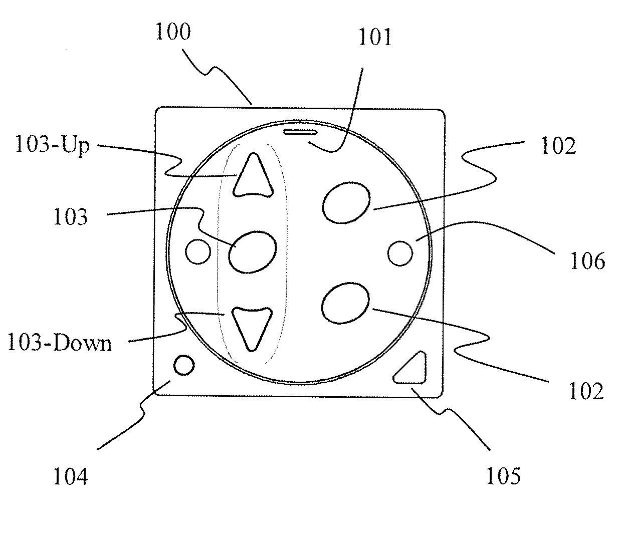
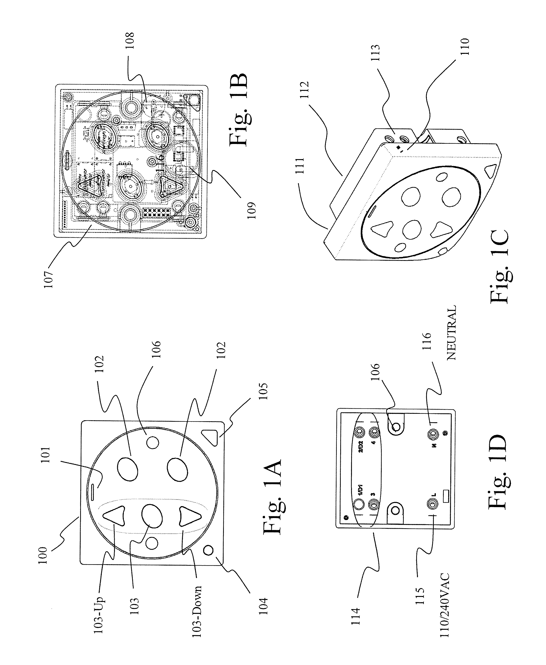
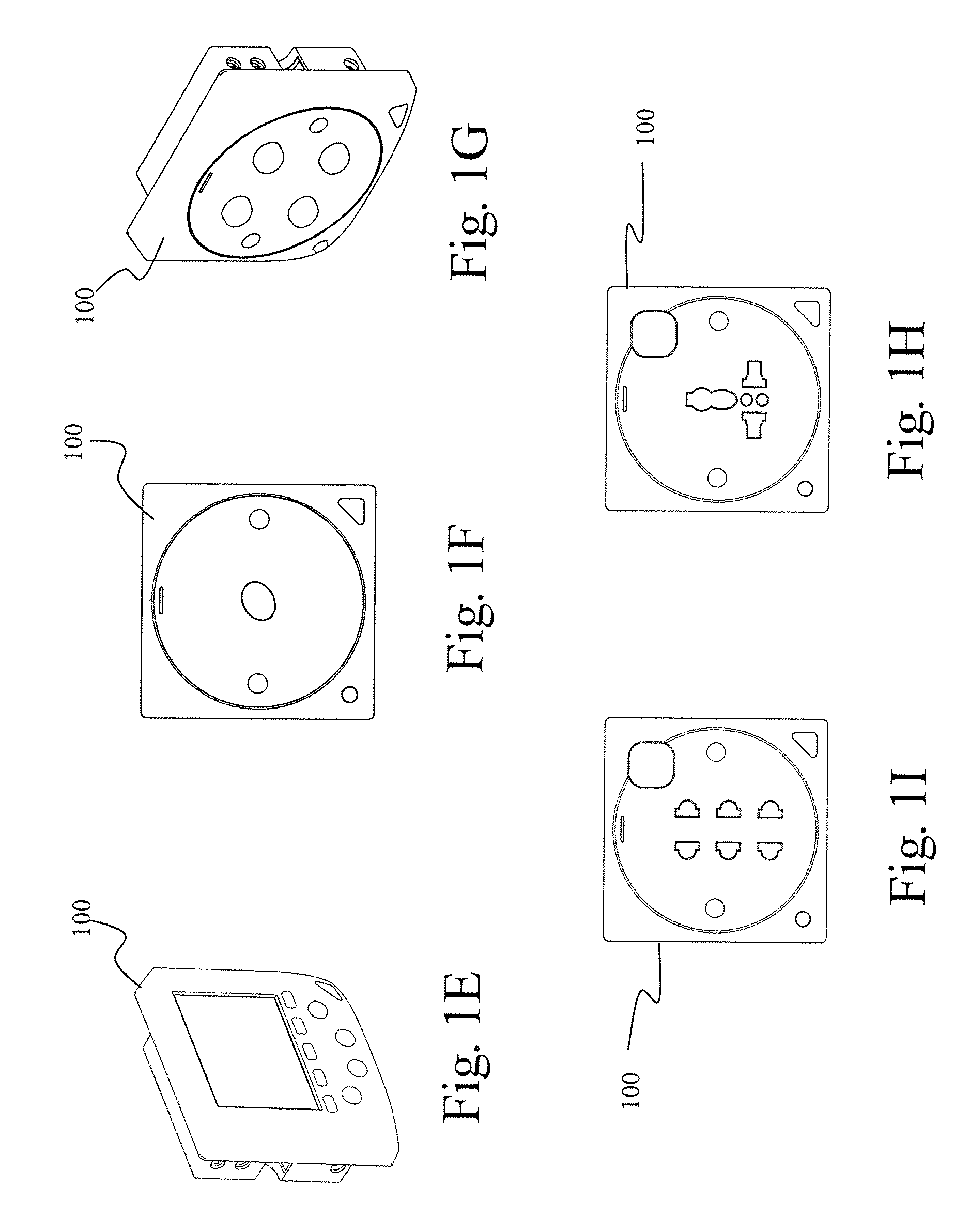
[0051]FIG. 1A is the front view of one embodiment of a microprocessor control switch panel 100. 101 is a light emitting diode (LED) visual indicator for line power and also as security alarm indicator. Below is a table for the different mode of 101 LED

Blue LightRed LightRemarksOFFOFFPower failure or power to microprocessor control switch panel100 is turned OFF.ONOFFLine power is available to all electronics andsecurity system is not activeOFFONWithout buzzer sound, security system is arm and readyWith buzzer sound, user is given a time delay to exit duringarming of secu...


PUM


Abstract

The present disclosure discloses an expandable wireless control system for and a method of managing and controlling building automation, lighting system, security system and electrical appliances. This system, based on a concept of modular mailboxes intercommunicating wirelessly by radio frequency and infrared frequency, can be used in new homes and buildings or easily retrofitted into existing homes and buildings without any need for massive rewiring, comprises of: microprocessor control switch panel, handheld remote devices, user input interface device, wireless multipurpose transceiver unit (MPU, 300) that interpose with remotely controllable subsystem of third party devices and electrical appliances to enable control of these devices to become a part of said system, and a wireless multipurpose transceiver with communication interface (MPUCOM, 302) in combination with a graphical user interface software that turns a personal computer into a setup computer, command centre, remote management gateway that connects to internet and telecommunication network (702).

Description

BACKGROUND [0001] 1. Field of Invention [0002] This present disclosure relates to an expandable wireless control system for and a method of managing and controlling building automation, lighting system, security system and electrical appliances. This system, based on a concept of modular mailboxes intercommunicating wirelessly by radio frequency and infrared frequency, can be used in new homes and buildings or easily retrofitted into existing homes and buildings without any need for massive rewiring. [0003] 2. Prior Art [0004] There are many known automation systems described in prior art that remotely control lighting and electrical appliances using handheld remote in tandem with centralized control panel either, wired, wireless or via power line carrier communication system. Many of the prior arts are centralized system—focused to be more expandable with increase mobility, more compatible and also to provide more competent control of increasingly sophisticated functions or even an...

Claims


Application Information

Patent Timeline
IPC IPC(8): H04M3/00
CPCH04L2012/2841H04L12/282
Inventor LOH, KUAM HONGLIM, HONG KENG
Owner NEWICT M
Learn More