
Acoustic noise reduction using airflow management

a technology of airflow management and acoustic noise reduction, applied in the field of computer systems, can solve the problems of overheating of electronic devices, failure of more fans cooling that particular device, and many electronic devices sensitive to heat, so as to reduce acoustic noise and reduce acoustic noise

Inactive Publication Date: 2007-12-20
GLOBALFOUNDRIES INC
View PDF11 Cites 36 Cited by
  • Summary
  • Abstract
  • Description
  • Claims
  • Application Information

AI Technical Summary

Benefits of technology

[0008]Embodiments of the invention address deficiencies of the art in respect to computer systems and provide a novel and non-obvious system and device for reducing acoustical noise generated by the computer system. The computer system includes a plurality of subsystems cooled by a cooling flow, at least one redirection device, a management module, and a blower for generating the cooling flow. The redirection device is associated with at least one subsystem and operable t

Problems solved by technology

Many electronic devices, however, are sensitive to heat, and as a result, many electronic devices include one or more fans to cool the devices.
An issue associated with these arrays of subsystems occurs when one of the electronic devices overheats.
The overheating may be for many reasons, but a typical reason for a subsystem to overheat is that one or more of the fans cooling that particular device have failed.
However, since the overheating device is in the midst of an array of other heat-producing devices, the issue of overheating is exacerbated.
Once the temperature of the subsystem rises to a certain level, the device may fail or failsafe measures may be employed.
Another issue associated with cooling the arrays of subsystems is that the device used to generate the flow of cooling fluid is limited by how fast the cooling device can operate.
Limits on the acoustical noise generated by computer devices have been imposed by OSHA, and these noise limits prevent current cooling devices from running faster and thus providing more cooling to the subsystems.

Method used


Image

  • Acoustic noise reduction using airflow management
  • Acoustic noise reduction using airflow management
  • Acoustic noise reduction using airflow management

Examples


Embodiment Construction

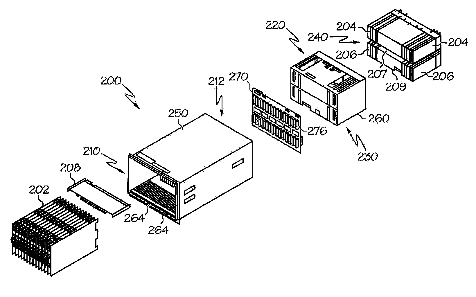
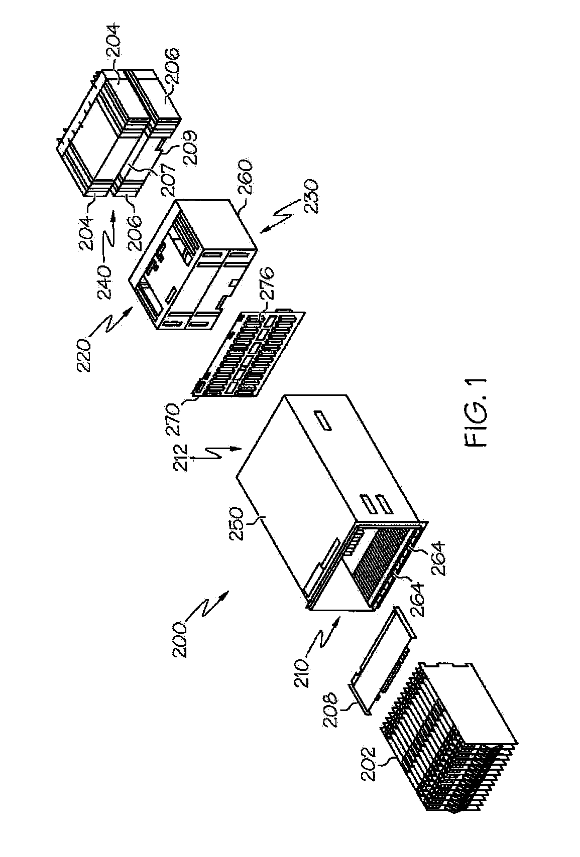
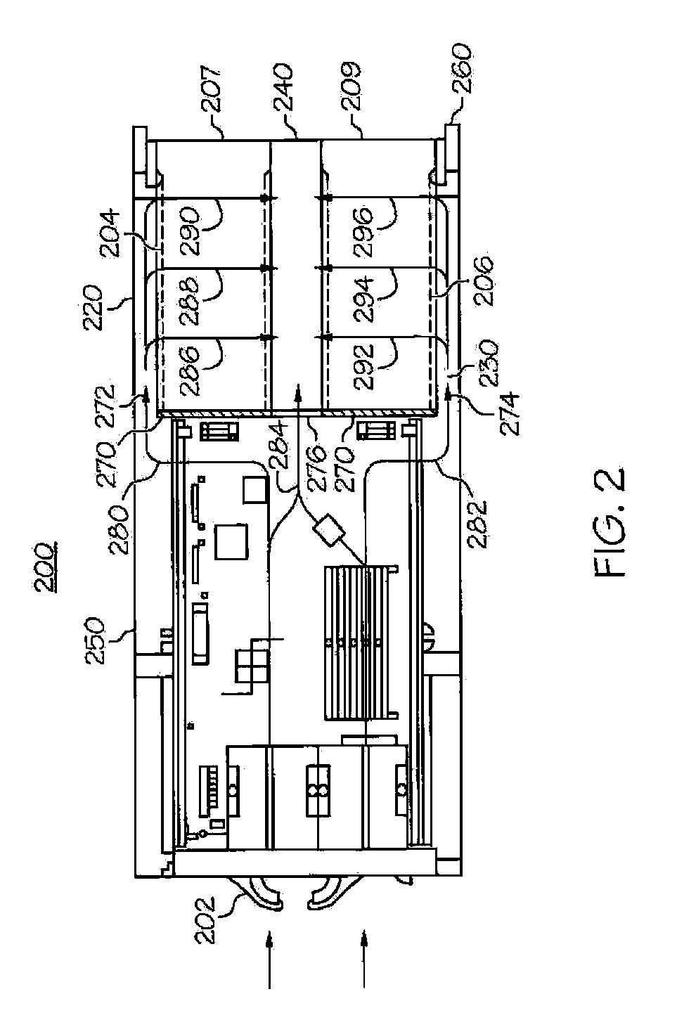
[0018]FIGS. 1-5 illustrate a acoustic noise and cooling management system 200. The system 200 includes a plurality of subsystems, such as blade servers 202 and peripheral devices 204, 206. cooled by an airflow; at least one redirection device 400; a management module 216; and a blower 207, 209 for generating the airflow. The redirection device 400 is associated with at least one subsystem and operable to redirect at least a portion of the airflow away from the subsystem 202, 204, 206. The subsystems 202, 204, 206, the at least one redirection device 400, and the blower 207, 209 are disposed along a common airflow path. The management module 216 is configured to determine cooling requirements of the subsystems 202, 204, 206 and to control the operation of the blower 207, 209 and the at least one redirection device 400 to maintain a specified amount of cooling to the subsystems 202, 204, 206 and to reduce acoustical noise generated by the blower 207, 209.

[0019]Referring to FIGS. 1 and...


PUM


Abstract

A computer system includes a plurality of subsystems cooled by a cooling flow; at least one redirection device, a management module, and a blower for generating the cooling flow. The redirection device is associated with at least one subsystem and operable to redirect at least a portion of the cooling flow away from the subsystem. The subsystems, the at least one redirection device, and the blower are disposed along a common cooling flow path. The management module is configured to determine cooling requirements of the subsystems and to control the operation of the blower and the at least one redirection device to maintain a specified amount of cooling to the subsystems and to reduce acoustical noise generated by the blower.

Description

BACKGROUND OF THE INVENTION[0001]1. Field of the Invention[0002]The disclosure relates generally to computer systems and, more specifically, to a computer system and device increasing the cooling to particular overheating devices in the computer system while also reducing the acoustic output of the computer system.[0003]2. Description of the Related Art[0004]Many type of electronic devices are assembled in arrays of subsystems. For example, a single blade center may include several blade servers arrayed one next to another. A byproduct of the operation of the electronic devices is heat, and since the array of electronic devices are typically located in a confined area, heat generated by a single electronic device affects neighboring electronic devices and vice-versa. Many electronic devices, however, are sensitive to heat, and as a result, many electronic devices include one or more fans to cool the devices.[0005]An issue associated with these arrays of subsystems occurs when one of...

Claims


Application Information

Patent Timeline
IPC IPC(8): H05K5/00G06F1/20H05K7/20
CPCG06F1/20H05K7/20836H05K7/20736G06F1/206
Inventor CRIPPEN, MARTIN J.HARPER, RICHARD E.KARIDIS, JOHN P.MAKLEY, ALBERT V.MATTESON, JASON A.PIAZZA, WILLIAM J.WARE, MALCOLM S.
Owner GLOBALFOUNDRIES INC
Learn More