Portable terminal equipment

a terminal and portability technology, applied in the field of portable terminal equipment, can solve the problems of wasting period of time for identifying the operation position of interest, affecting the operation of the touch panel, and affecting the user's ability to accurately grasp the location of the touch panel where the finger is placed, so as to achieve the effect of improving operability and easy operation and accurately

Inactive Publication Date: 2007-12-20
SONY CORP
View PDF33 Cites 66 Cited by
  • Summary
  • Abstract
  • Description
  • Claims
  • Application Information

AI Technical Summary

Benefits of technology

[0015]Even if an image is displayed on the display panel, the user can grasp a location relationship between this image and his or her finger(s) through the image. It, thus, is possible to identify the operation location in the touch sensor to be operated easily and accurately. The user's hand and / or finger does not block his or her view from the displayed image since, in this embodiment, the operation position in the touch panel is not identified from the front side of the display panel. As the plane display device made of a transparent or translucent material, an organic electroluminescent (EL) element or the like can be used.
[0016]According to the embodiment of this invention, the user can select one from switches or pieces of displayed information of interest easily by touching the touch sensor by his or her finger or the like from the rear side of the display panel while he or she views the image(s) displayed on the display panel. Thus, its operability can be improved without blocking the image displayed on a screen of the display panel by his or her hand or hands.

Problems solved by technology

In this moment, it is difficult to visually identify the operation position in the touch panel mounting the display panel through the display panel.
Further, before the touch panel is touched, no cursor appears on the screen of the display panel so that it is difficult for the user to get an accurate grasp which location in the touch panel his or her finger is put on.
This may cause a period of time for identifying the operation position of interest to be wasted because of its difficult immediate operability.

Method used


Image

  • Portable terminal equipment
  • Portable terminal equipment
  • Portable terminal equipment

Examples


Embodiment Construction

[0031]The following will describe preferred embodiments of portable terminal equipment according to the invention with reference to the attached drawings.

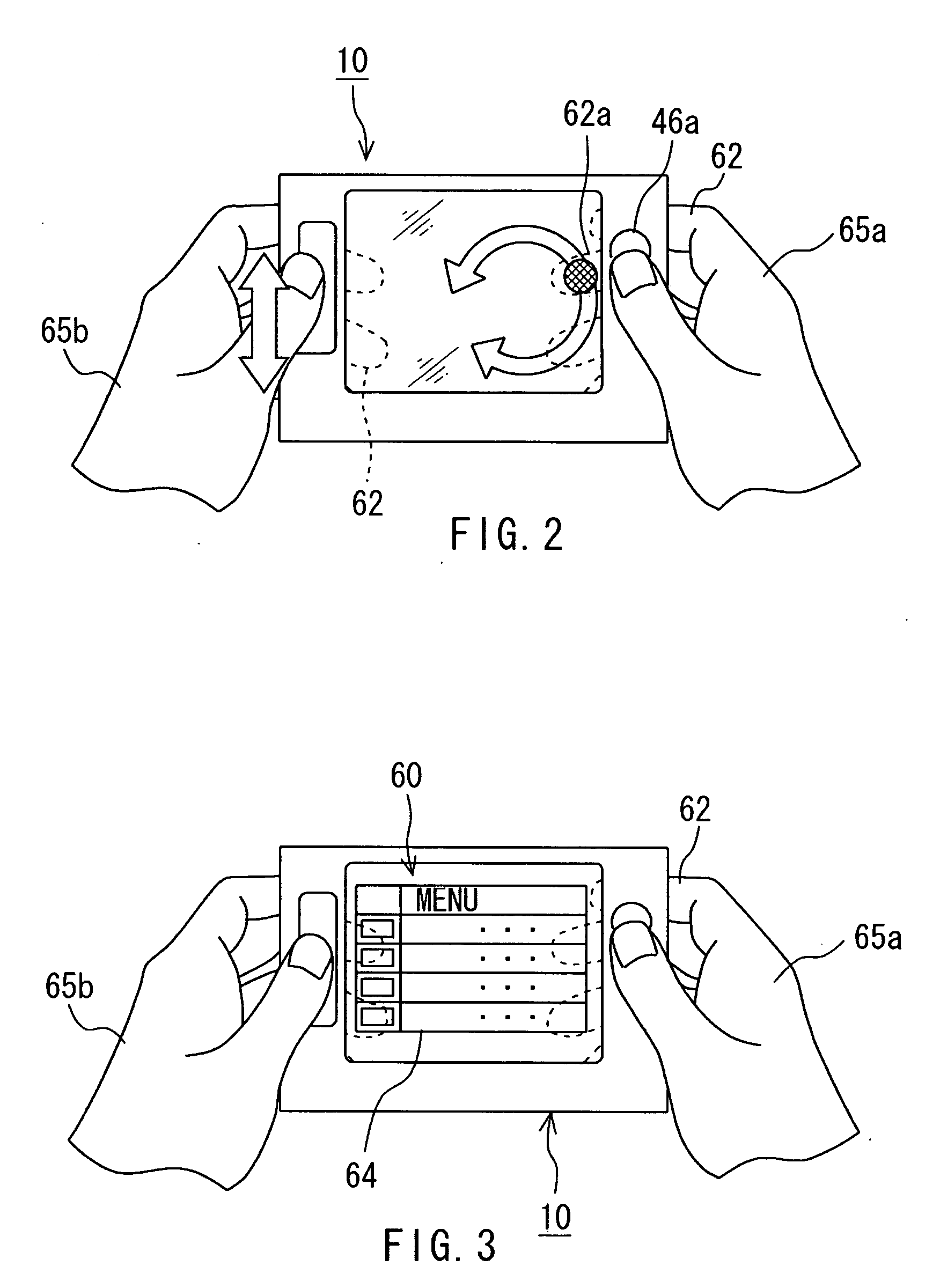
[0032]FIG. 1 illustrates an important portion of an embodiment of portable terminal equipment 10 according to the invention.

[0033]This portable terminal equipment 10 is constituted of transparent plane display device 20, a touch sensor 30 (touch screen) mounting the transparent plane display device 20, and a casing 40 that holds the plane display device 20 by sandwiching the plane display device 20 therebetween from both of upper and lower sides of the plane display device 20.

[0034]The plane display device 20 contains a transparent plane display panel 21 that emits light by itself, namely, is light-emitting device, and a control circuit board 44 as a display-driving mechanism therefor. The control circuit board 44 can be installed on the display panel 21. FIG. 1, however, illustrates a case where the control circuit board 44 is sep...


PUM


Abstract

Portable terminal equipment contains plane display device made of a transparent or translucent material and a touch sensor made of a transparent or translucent material. The touch sensor mounts the plane display device. The portable terminal equipment also contains a casing that holds the plane display device by fastening the plane display device from both sides thereof.

Description

CROSS REFERENCE TO RELATED APPLICATION[0001]The present invention contains subject matter related to Japanese Patent Application JP 2006-169 filed in the Japanese Patent Office on Jun. 19, 2006, the entire contents of which being incorporated herein by reference.BACKGROUND OF THE INVENTION[0002]1. Field of the Invention[0003]This invention relates to portable terminal equipment such as a personal digital assistant (PDA) or a mobile telephone.[0004]2. Description of Related Art[0005]Terminal equipment has been developed as compact and lightweight information-processing device. Portable terminal equipment such as PDA having a display area of a display panel for displaying any information as large as possible has also been developed.[0006]On such the portable terminal equipment, a user manipulates any input operations by means of touch of his or her fingertip or a stylus on a screen of the display panel in the display device with a body of the portable terminal equipment being held by ...

Claims


Application Information

Patent Timeline
Patent Type & Authority Applications(United States)
IPC IPC(8): G06F3/041
CPCG06F1/1626G06F3/04886G06F3/0488G06F1/169
Inventor MORI, EIJIRO
Owner SONY CORP
Why Eureka
Try Eureka