
Roller Assembly

a technology of rollers and assemblies, which is applied in the direction of multi-purpose tools, door/window fittings, construction, etc., can solve the problems of frequent replacement of parts, significant wear and tear of rollers of doors, and the need for frequent maintenance of doors, so as to achieve cost-effective production, operation and maintenance.

Inactive Publication Date: 2007-12-20
CRECO A OHIO
View PDF16 Cites 7 Cited by
  • Summary
  • Abstract
  • Description
  • Claims
  • Application Information

AI Technical Summary

Benefits of technology

[0007]Preferred embodiments of the roller assembly also include a washer, preferably made of a polymer and situated on the shaft in between a ferrule and a shoulder disposed on the shaft. The roller is preferably made of a polymer, and the ferrule is preferably made of metal, and the shaft is preferably made of metal. Also, in the preferred embodiments, the shaft is cold-headed at its distal end so as to prevent the roller from falling off of the shaft. However, the roller may be secured to the shaft by any appropriate means.
[0009]One significant advantage of the roller assembly of the present invention is that it does not need ball bearings. Also, the roller assembly has relatively few parts, does not require glue or special fixtures to assemble, and therefore it is cost-effective to produce, operate, and maintain. The roller assembly of the present invention exhibits long life, and during operation it is relatively quite as compared to the all metal roller assemblies of the prior art.

Problems solved by technology

Nevertheless, frequent use results in significant wear and tear on the rollers of these doors.
Parts thus need frequent replacing, and the doors need frequent maintenance.
This, in turn, results in down time, expense, and reduction in efficiency for the users of these doors.

Method used


Image

  • Roller Assembly
  • Roller Assembly
  • Roller Assembly

Examples


Embodiment Construction

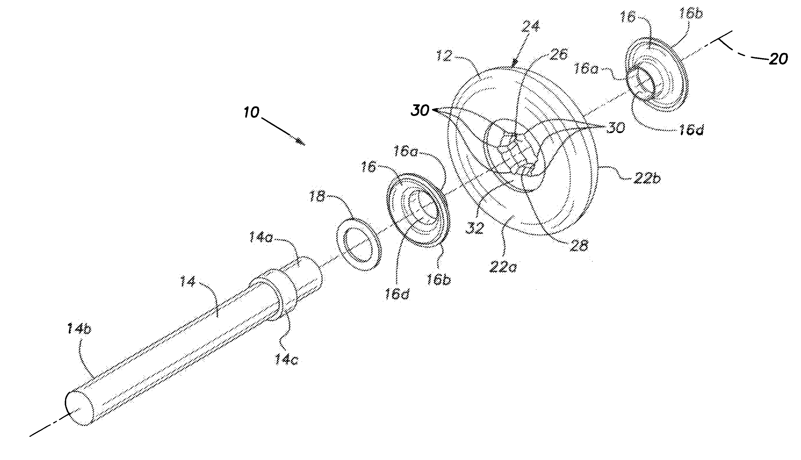
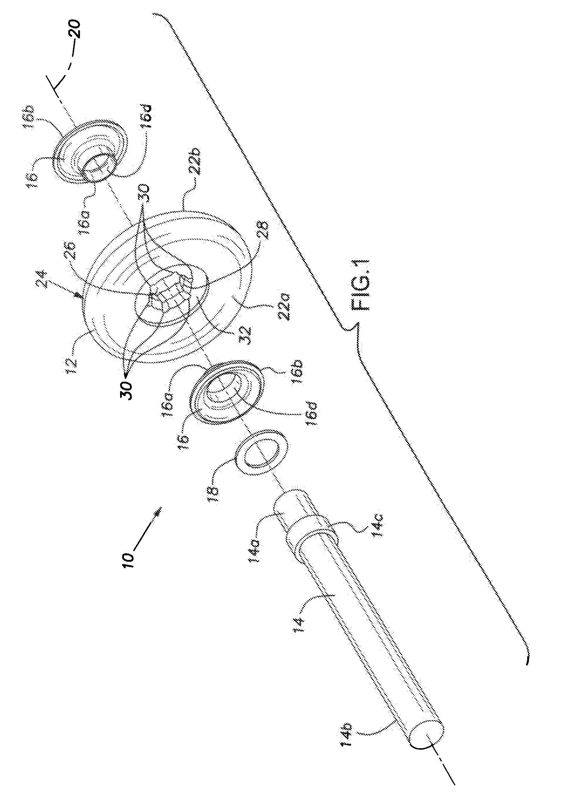
[0022]FIG. 1 shows an exploded perspective view of one embodiment of a roller assembly 10 of the present invention. The roller assembly 10 basically comprises a roller 12, a shaft 14, and one or more ferrules 16. Preferably, as shown in FIG. 1, there are two ferrules 16. Also, in the preferred embodiments, a washer 18 is part of the roller assembly 10. All of these parts are assembled along an axis 20 so as to allow the roller 12 to rotate around the axis 20. The roller assembly 10 of the present invention is especially well suited for use in a flexible over head door such as a garage door or a rolling over head door on a commercial truck.

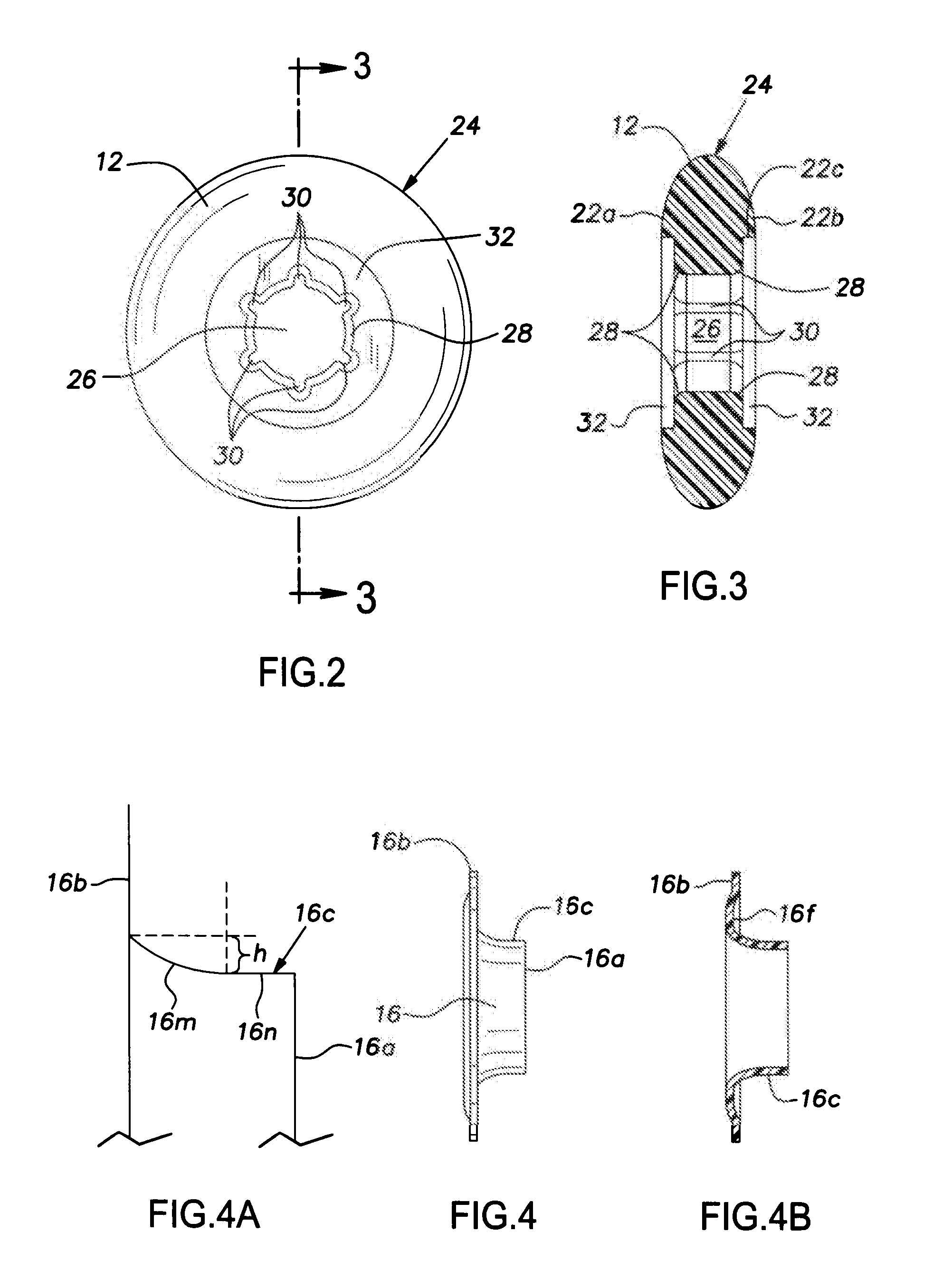
[0023]As can be seen, for example, in FIGS. 1-3, the roller 12 has first and second sides 22a and 22b, a rolling surface 24, and an interior bore 26 extending through the roller 12 and centered along the axis 20. The diameter of the interior bore 26 allows the shaft 14 to fit within the bore, as will be explained further herein. The rolling surface...


PUM


Abstract

A roller assembly for a rolling door or similar device. The roller comprises a polymer and it has first and second sides, a rolling surface, and an axis around which the roller rolls. The roller also has an interior bore and a shaft rotatably coupled to the roller. One or more ferrules are received within one or both sides of the roller. The ferrules support and align the roller for rotation upon the shaft.

Description

BACKGROUND OF THE INVENTION[0001]1. Field of the Invention[0002]The present invention relates to roller assemblies, and, more particularly, to roller assemblies used in conjunction with flexible over head doors such as those found in garages and trucks.[0003]2. Description of Related Art[0004]A common type of flexible over head door has several elongated segments that are hinged together to form an enclosure for an opening or entrance to a building, commercial truck, or other enclosable area. The elongated segments typically have rollers secured to their lateral sides so as to allow the over head door to roll up and down within linear tracks located at each side of the enclosure. This configuration allows the door to roll from a vertical, lowered position to a horizontal, raised position, thereby allowing the door to open and close.[0005]Many types of flexible over head doors are used in commercial environments and are therefore raised and lowered several times a day. In many types ...

Claims


Application Information

Patent Timeline
Patent Type & Authority Applications(United States)
IPC IPC(8): A47H15/00
CPCE05D15/165Y10T16/364E05Y2900/132E05Y2201/688
Inventor ESPEY, CARL R.
Owner CRECO A OHIO
Learn More