Clean energy generation system

Inactive Publication Date: 2007-12-13
CAFARIELLO JOSEPH
View PDF10 Cites 31 Cited by
  • Summary
  • Abstract
  • Description
  • Claims
  • Application Information

AI Technical Summary

Benefits of technology

[0006]It is thus the object of the present invention to provide mankind with water-powered electrical generation systems that are inexpensive to implement, non-obtrusive to the ecosystems, and as invisible and aesthetically pleasing as possible.
[0008]Accordingly, the device of the present invention therefore provides mankind with electrical power generation systems that are inexpensive, non-obtrusive and as invisible as possible.

Problems solved by technology

For the most part, these systems have been very costly to implement and require a higher level of maintenance to function properly.
Furthermore, most prior art systems alter or deface the natural landscape.
Additionally, the ecosystem is greatly affected by these installations.

Method used


Image

  • Clean energy generation system
  • Clean energy generation system
  • Clean energy generation system

Examples


Embodiment Construction

[0016]In the following description, similar features in the drawings have been given similar reference numerals.

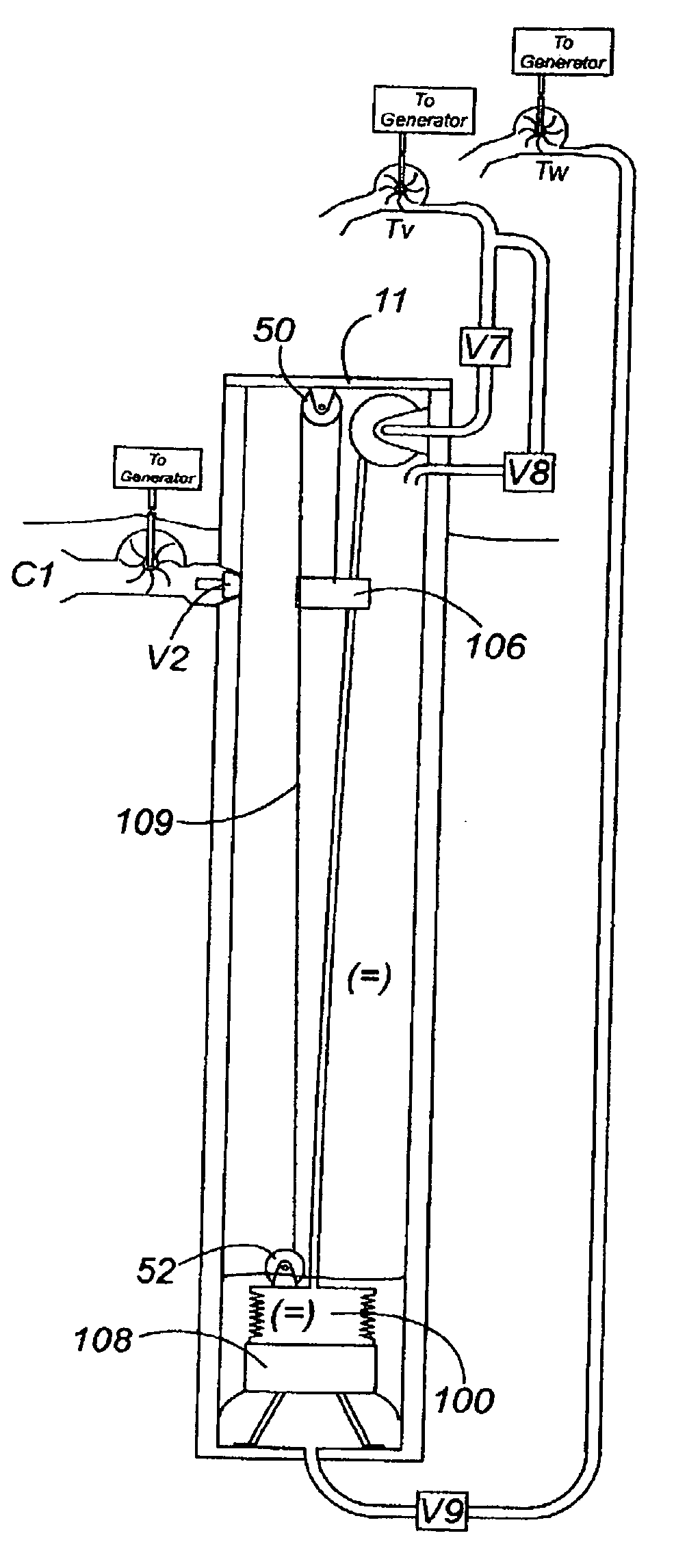
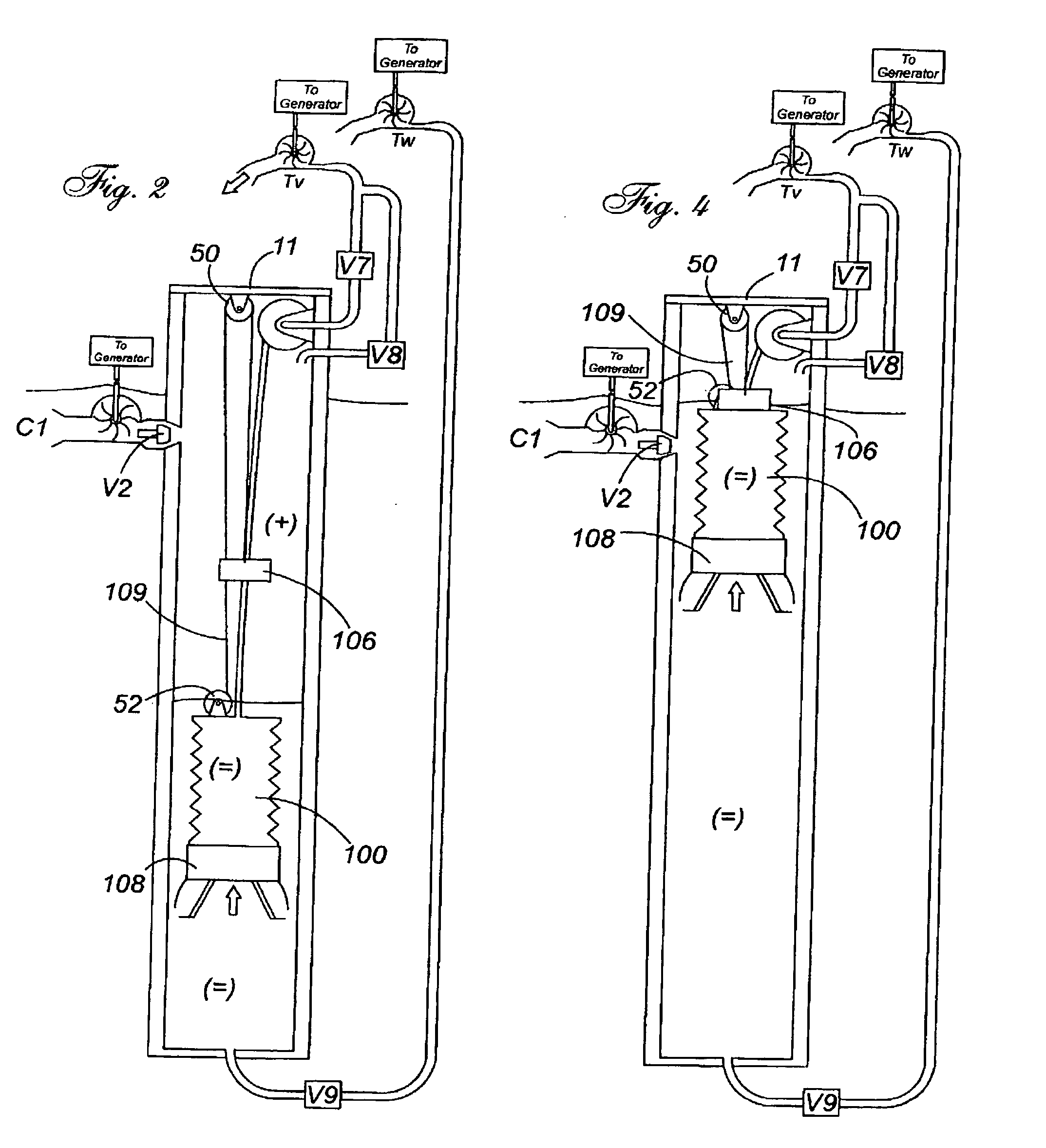
[0017]Turning to FIGS. 1 through 4, all semi-transparent front elevation views of the clean energy generation system of the present invention illustrated at stages 1 through 6 wherein the bladder assembly 100 has a lower weight 108. An upper weight 106 is fixedly attached to a tether 109. The upper weight 106 serves to apply downward pressure onto the bladder 100 so as to deplete said bladder 100 of the air within. An accumulator reel 52 located atop the bladder collects excess tether 109 and said tether 109 is rotably attached to the underside of the upper cap 11 of the chamber via a pulley 50 thus maintaining light tension on the tether 109.

[0018]In FIG. 1, all systems are in reset mode and all valves V2, V7, V8, and V9 are closed. Equilibrium is reached. Reel 50 is locked and the upper weight 106 is suspended.

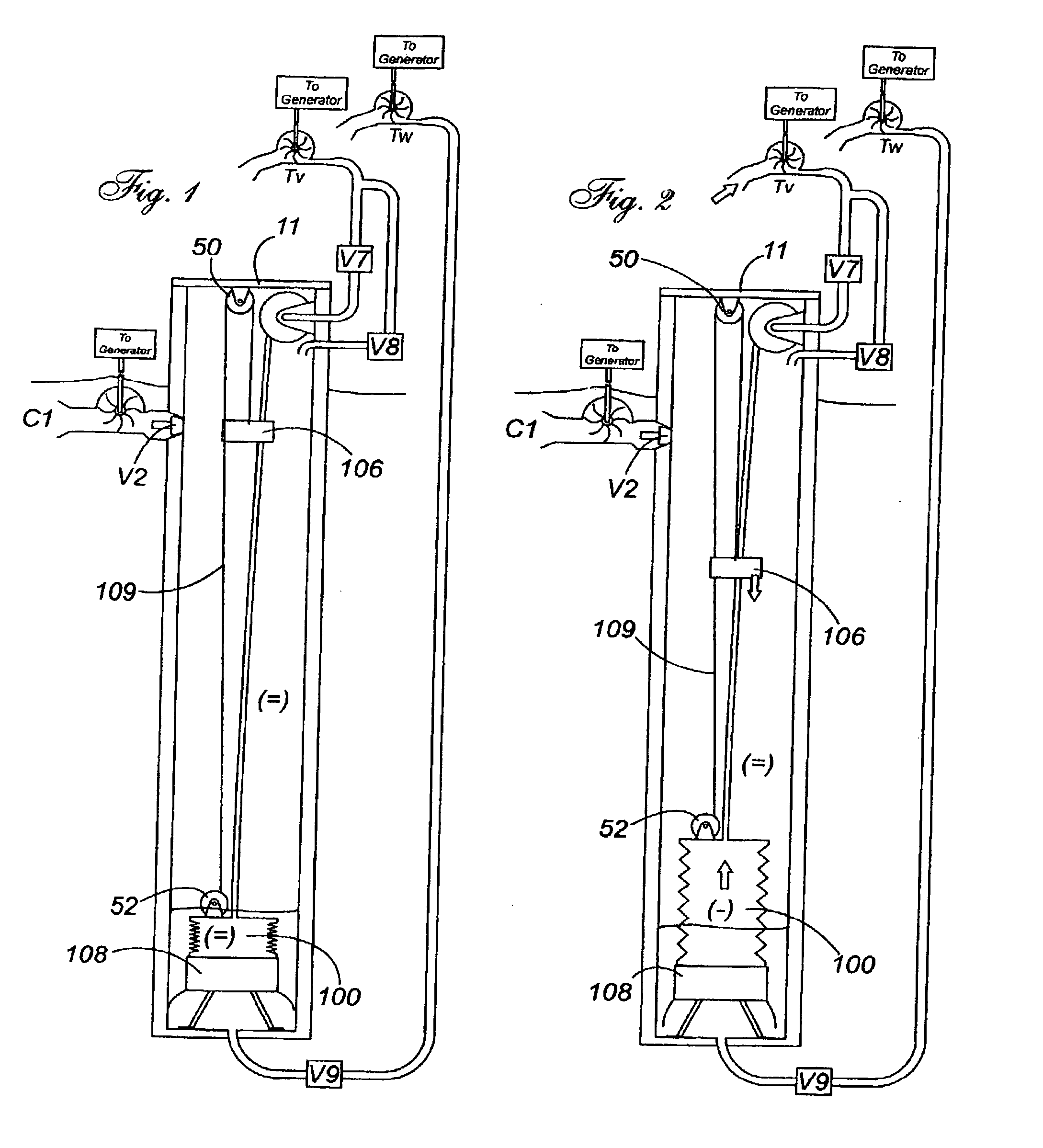
[0019]In FIG. 2, reel 50 is rotable, reel 52 is locked, valve...


PUM


Abstract

The present invention relates to an inexpensive system for the production of clean energy. The system of the present invention comprises a chamber system utilizing active buoyancy of a weighted bladder to pressurize and vacuum air within said chamber thus driving rotary impellers for actuation of one or more electrical or mechanical generators.

Description

FIELD OF THE INVENTION[0001]The present invention relates to an inexpensive system for the production of clean energy. The system of the present invention comprises a chamber system utilizing active buoyancy of a weighted bladder to pressurize and vacuum air within said chamber thus driving rotary impellers for actuation of one or more electrical or mechanical generators.BACKGROUND OF THE INVENTION[0002]Power generation is a vital subject in meeting today's ever-increasing energy consumption needs, and along with many other methods, water powered systems have also been implemented for the generation of electrical power. For the most part, these systems have been very costly to implement and require a higher level of maintenance to function properly. Furthermore, most prior art systems alter or deface the natural landscape. Additionally, the ecosystem is greatly affected by these installations.[0003]The inventor sought to provide mankind with systems that are inexpensive, non-obtrusi...

Claims


Application Information

Patent Timeline
IPC IPC(8): F03B13/00H02P9/04
CPCF03B17/00Y02E10/20F03B17/04
Inventor CAFARIELLO, JOSEPH
Owner CAFARIELLO JOSEPH
Why Eureka
Try Eureka