
Fluid dynamic power generator and methods

a technology of fluid dynamics and power generation system, applied in the field of fluid dynamic power generation system, can solve the problems of limited application of fluid dynamics principles to the field of power generation described in terms of equations 3 and 4, requires relatively high temperatures for their operation, and a significant amount of heat to the body of fluid, so as to achieve clean source of useable power and high kinetic energy

Inactive Publication Date: 2007-12-06
SORENSON SIDNEY DALE
View PDF10 Cites 11 Cited by
  • Summary
  • Abstract
  • Description
  • Claims
  • Application Information

AI Technical Summary

Benefits of technology

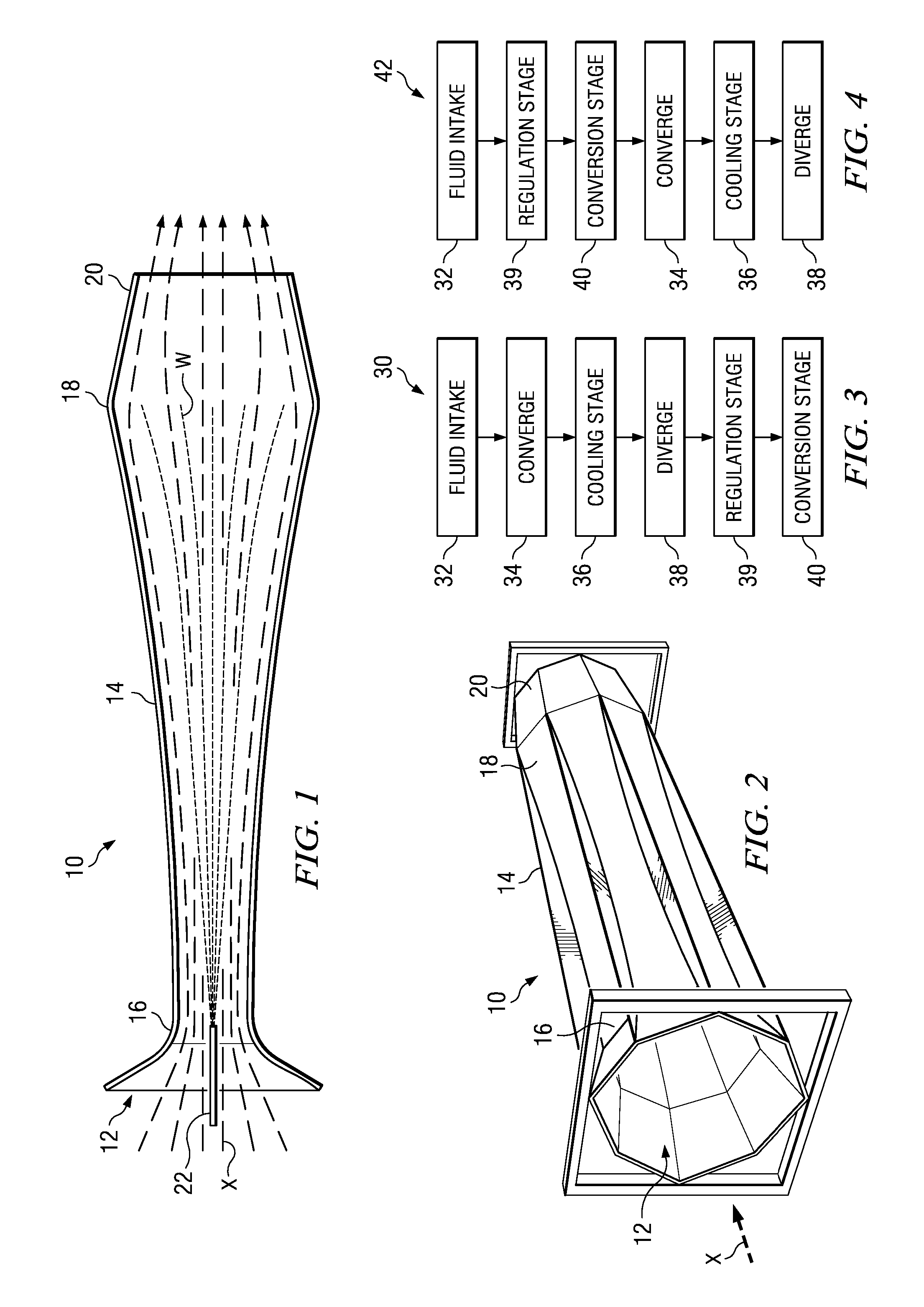
"The present invention provides a power generation method and apparatus that uses fluid media to generate useable power. The method involves introducing a fluid into a convergent-divergent stream duct, where it is accelerated and cooled before being ejected through a variable area exhaust port. The ejected fluid has higher kinetic energy than the intake fluid. The invention has advantages of providing a clean source of useable power generated from relatively low intensity input."

Problems solved by technology

Application of the principles of fluid dynamics to the field of power generation described in terms of Equations 3 and 4 has been limited, and has met with several problems.
Prior art efforts at using the principles of fluid dynamics to extract useable energy from changes in stagnation pressure have required relatively high temperatures for their operation.
Unfortunately, maintaining this speed over an appreciable distance requires the application of a significant amount of heat to the body of fluid, in this case gas, which is not always practical.
Another problem with the approaches used in the prior art is that each used supersonic flow at the throat to limit flow rates.
This practice is problematic for a low temperature generator.
Under most conditions it will reach dew point long before it reaches or exceeds Mach 1, resulting in a wet gas.
Accelerating a wet gas results in significant energy losses, therefore the gas temperature must be below dew point at the injection point and thus significantly less than Mach 1 under most conditions.

Method used


Image

  • Fluid dynamic power generator and methods
  • Fluid dynamic power generator and methods
  • Fluid dynamic power generator and methods

Examples


Embodiment Construction

[0021] In general, the invention provides a fluid-dynamic power generator apparatus and associated methods which overcome the foregoing and other practical problems which have long since characterized the prior art. In accordance with the broader aspects of the invention, a fluid-dynamic power generator preferably operates utilizing either dry or wet exhaust, thereby enabling the use of fluid media that includes liquids that do not completely evaporate. By utilizing liquids that do not completely evaporate, the invention can operate using widely available and inexpensive coolants such as, for example, water and brine, and can be operated with input fluid temperatures as low as 70° F. provided that the dew point is at least 10° F. less than the fluid input temperature. The greater the differential between the temperature and dew point, the more efficient the generator.

[0022] The apparatus and methods of the present invention are capable of achieving useable power levels with efficie...


PUM


Abstract

Fluid dynamic power generation methods and associated apparatus are disclosed for introducing a fluid through an intake into a convergent-divergent stream duct adapted for accelerating the fluid. The fluid is cooled within the convergent-divergent stream duct and ejected through a variable area exhaust port, the ejected fluid having a higher kinetic energy than the intake fluid, for conversion to useable power.

Description

PRIORITY ENTITLEMENT [0001] This application claims priority based on Provisional Patent Application Ser. No. 60 / 727,101 filed on Oct. 14, 2005, incorporated herein for all purposes. This application and the aforementioned Provisional patent application have a common inventor.TECHNICAL FIELD [0002] The invention relates to power generators and methods for using fluid media for power generation. More particularly, the invention relates to fluid dynamic power generation systems and methods operable at relatively low temperatures. A water cooled fluid dynamic generator of the invention is capable of yielding useful quantities of mechanical energy from relatively low intensity energy sources such as, for example, ambient air driven by wind. BACKGROUND OF THE INVENTION [0003] The following equations may be helpful in understanding the application of some of the principles of the basic physics of fluid dynamics as they relate to the art and practice of the present invention. The engine de...

Claims


Application Information

Patent Timeline
Patent Type & Authority Applications(United States)
IPC IPC(8): F02K3/00B64G1/40
CPCF03G7/10F03G7/00F03G7/0254F03G7/129
Inventor SORENSON, SIDNEY DALE
Owner SORENSON SIDNEY DALE
Learn More