
Continuous motion packaging system

a continuous motion and packaging technology, applied in the field of cartons, can solve the problems of increasing the cost of materials and manufacturing, increasing the cost of shipping such carton sleeves in cases, and occupying a significantly larger amount of spa

Inactive Publication Date: 2007-12-06
GRAPHIC PACKAGING INT
View PDF22 Cites 28 Cited by
  • Summary
  • Abstract
  • Description
  • Claims
  • Application Information

AI Technical Summary

Benefits of technology

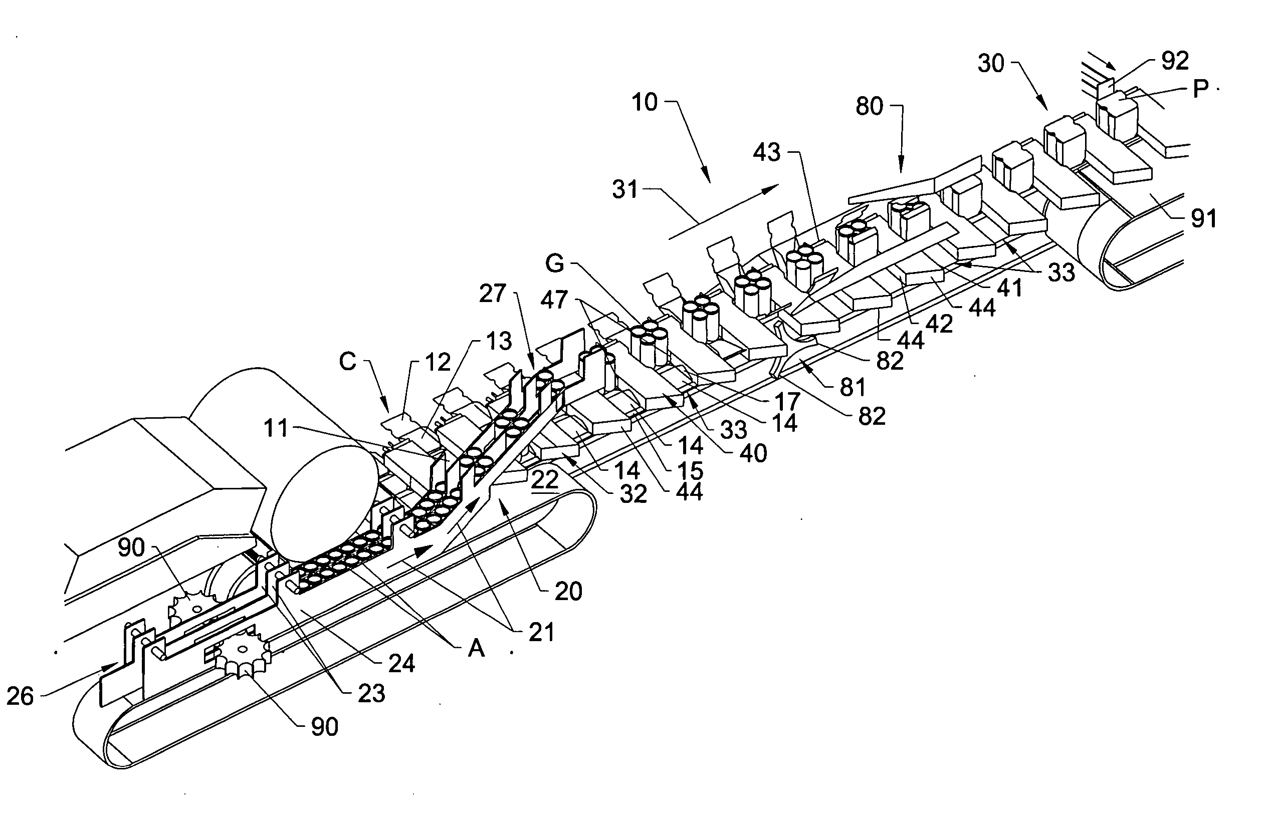
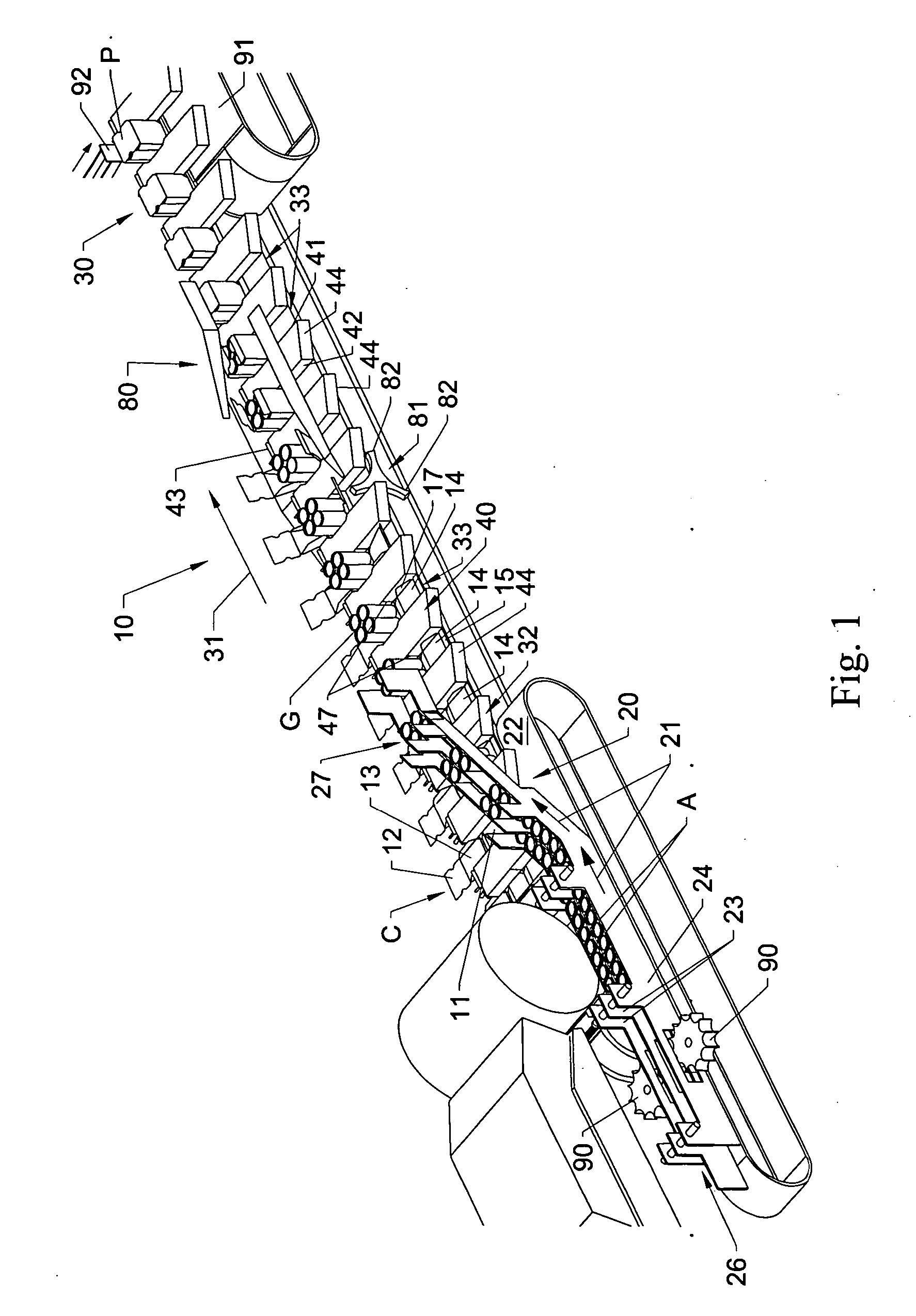
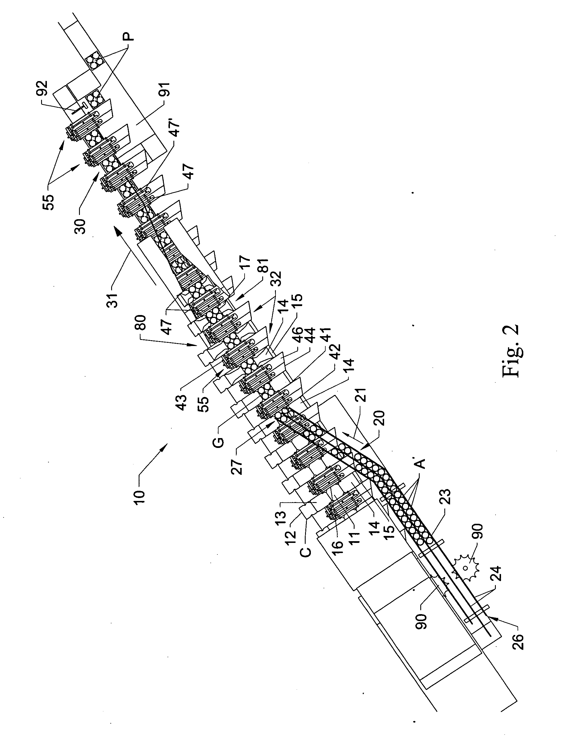
[0007] As the articles move along their article infeed path toward the loading position, the selector wedges engage and separate the articles to form article groups received on the base panels of the cartons within the flights of the carton conveyor. As the cartons continue along their packaging path with a selected group of articles received thereon, top and end panels of the cartons are engaged by guiding or folding mechanisms that fold or urge the end and top panels of the cartons toward the group of articles thereon. At approximately the same time, one or more gusset tucking fingers arranged along the upstream end and / or downstream sides of the selector wedges can be reciprocated or extended outwardly from the selector wedges toward an engaging position so as to contact and urge or tuck gusset portions of the cartons inwardly. Tucking of the gussets helps cause the side panels of the cartons to fold likewise inwardly against the groups of articles.

Problems solved by technology

One drawback of utilizing cartons into the pre-glued sleeves for product packaging applications, however, is that such pre-formed sleeves typically are more expensive to produce than conventional stamped or die cut wrapped carton sheets.
After stamping or cutting, the carton blanks must be folded and their side edges glued together to form the carton sleeves, which accordingly results in increased costs from a materials and manufacturing standpoint, due to the additional glue required to form the sleeves, and in the need for additional folding and gluing equipment.
As a result, shipping such carton sleeves in cases typically takes up a significantly greater amount of space when stacked on pallets for transportation and storage.
This can require additional material handling to arrange and stack the cartons in cases, which, with the cost of the case, further increases the costs of manufacture thereof.
However, applying or wrapping such flat blank cartons about products typically can require more precision in the handling, folding, and tucking of the carton panels and locking mechanisms or flaps during formation of the cartons about the products, thus, slowing production rates.

Method used


Image

  • Continuous motion packaging system
  • Continuous motion packaging system
  • Continuous motion packaging system

Examples


Embodiment Construction

[0016] Referring now in greater detail to the drawings in which like numerals indicate like parts throughout the several views, FIGS. 1-4 generally illustrate one example embodiment of a continuous motion packaging system 10 according to the principles of the present invention. While the present invention is generally illustrated in FIGS. 1-4B, as packaging a series of cans, it will be understood by those skilled in the art that various other products or articles A such as bottles, boxes, or other, similar products can be wrapped or otherwise packaged in cartons C moving through the continuous motion packaging system 10 of the present invention. The cartons C typically will comprise flat blank, wrap style cartons that are designed to fold or be otherwise wrapped about a series of articles received on a bottom or base panel 11 of each carton. The cartons will each include base panel 11, a first or main top panel 12, end panels 13 and 14, and a second top panel 15, which can be folded...


PUM


Abstract

A continuous motion packaging system for packaging a series of articles in cartons as the cartons are moved along a carton conveyor. A series of selector wedges engage and form groups of articles received on the cartons, which are folded or wrapped about the articles as the cartons are moved forwardly along a packaging path.

Description

FIELD OF THE INVENTION [0001] The present invention generally relates to cartons and other containers for packaging articles therein, and in particular, to a system for packaging various types of articles in cartons folded about groups of products in a substantially continuous motion process. BACKGROUND OF THE INVENTION [0002] In the packaging of products such as bottles, cans, pouches or other similar articles, it is common for such products to be packaged in paperboard cartons, such as to form twelve packs, twenty-four packs, or other similar package configurations. Such cartons can be fed into a packaging machine and wrapped about the products or articles being packaged, with the lower or bottom edges of the cartons folded under and either glued or locked together by the engagement of locking tabs with locking recesses formed therein. Alternatively, for packaging selected groups of products, such as twelve packs of cans or bottles, or for packaging other larger and / or irregularly...

Claims


Application Information

Patent Timeline
IPC IPC(8): B65B35/30B65B21/24
CPCB65B5/068B65B21/242B65B11/105
Inventor FORD, COLIN P.
Owner GRAPHIC PACKAGING INT
Learn More