
System and method for providing continuous data protection

a data protection and continuous technology, applied in the field of storage systems, can solve the problems of unprotected and therefore unrecoverable, introduce a level of undesirable latency into the pcpi creation process, and concomitant increase, and achieve the effect of optimizing the use of parity disks

Active Publication Date: 2007-11-29
NETWORK APPLIANCE INC
View PDF62 Cites 77 Cited by
  • Summary
  • Abstract
  • Description
  • Claims
  • Application Information

AI Technical Summary

Benefits of technology

[0021] The user interfaces are modified to allow users or applications to specify any point in time for accessing data contained in checkpoints. This any point in time interface permits users to access checkpoints without having to know the exact creation time of the checkpoint. When the specified time does not match the creation time of any checkpoint, the immediately preceding checkpoint created prior to the specified time is utilized. Such interfaces also have the advantage of being able to accommodate finer granularity.

Problems solved by technology

Any changes that occur during CPs between PCPIs are not protected and are therefore not recoverable.
PCPIs may be generated on a more frequent basis; however, a noted disadvantage of more frequent PCPI generation is that the creation of each PCPI requires the logical OR'ing of each of the summary maps from each PCPI to create the summary map for the active file system.
In an example of a storage system supporting 255 PCPIs, the time required to perform this logical OR operation may introduce a level of undesirable latency into the PCPI creation process.
Thus, by increasing the number of PCPIs retained, there is a concomitant increase in the time required to perform the logical OR operations at each PCPI creation, thereby increasing the overall latency of the storage system.
If a PCPI were to be created at each CP, the performance of the storage system would quickly degrade to an unacceptable level.

Method used


Image

  • System and method for providing continuous data protection
  • System and method for providing continuous data protection
  • System and method for providing continuous data protection

Examples


second embodiment

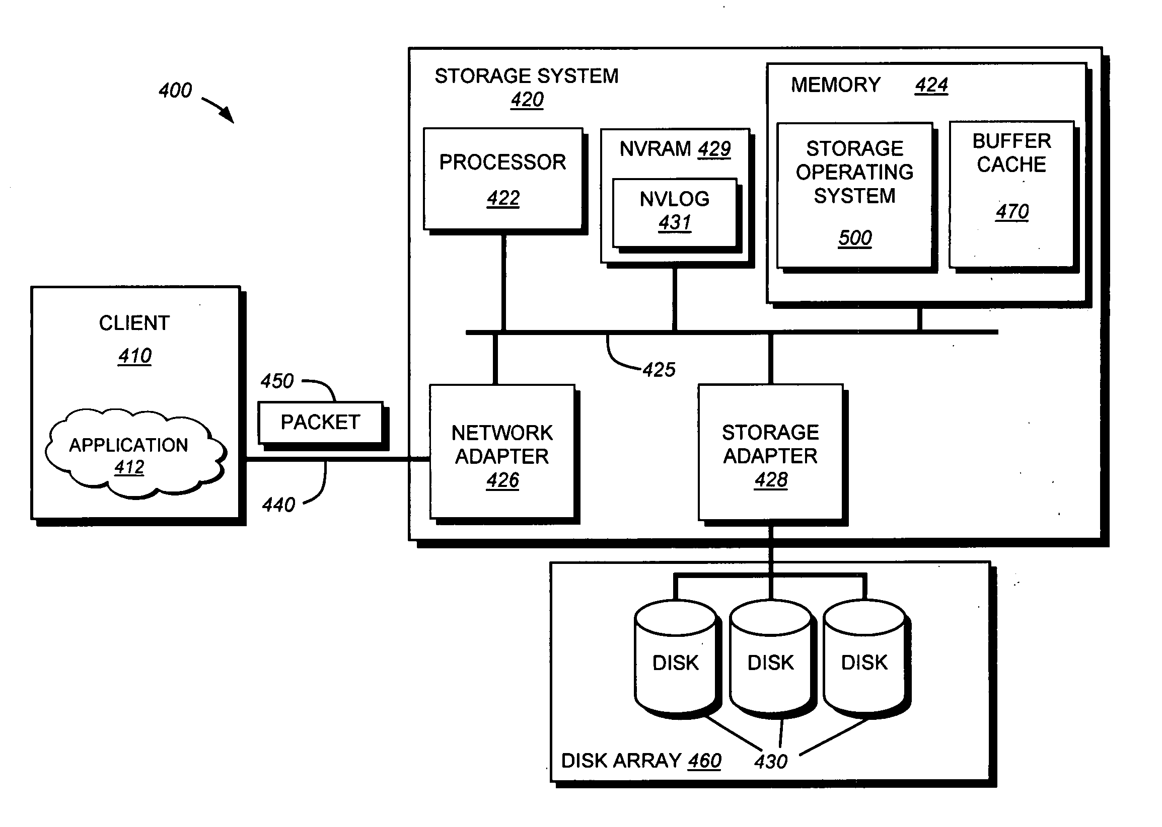
[0042] In the illustrative embodiment, the memory 424 comprises storage locations that are addressable by the processor and adapters for storing software program code. A portion of the memory may be further organized as a “buffer cache”470 for storing data structures associated with the present invention. Additionally the NVRAM 429 may be utilized for storing changes to the file system between consistency points. Such changes may be stored in a nonvolatile log (NVLOG) 431 that is, during the course of a consistency point, flushed (written) to disk. In accordance with the present invention, the contents of the NVLog 431 are stored within a file operations log, which enables a storage system user to determine the ordering of operations received by the storage system. The processor and adapters may, in turn, comprise processing elements and / or logic circuitry configured to execute the software code and manipulate the data structures. Storage operating system 500, portions of which are ...

first embodiment

[0085]FIG. 10 is a flowchart detailing the steps of a procedure 1000 for creating a check-point during a CP in accordance with the present invention. The procedure 1000 begins in step 1005 and continues to step 1010 where a CP is initiated. The CP may be initiated due to, for example, the expiration of a timer, the filling of incore memory for storing changes, by an administrator command, etc. During the course of the CP, write allocation is performed in step 1015. Write allocation is described in the above-incorporated U.S. Pat. No. 5,819,292. During the course of write allocation, various volume (or virtual volume) blocks may be freed, due to deletion of a file, a change in data causing the write anywhere file system to rewrite the modified block to a new location, etc.

[0086] The file system identifies these freed blocks in step 1020. illustratively, during write allocation, the file system generates a list of blocks that have been freed. The file system then updates the CP log in...


PUM


Abstract

A system and method provides continuous data protection using checkpoints in a write anywhere file system. During a consistency point of a write anywhere file system, freed blocks are identified and are appended to a delete log for retention. A consistency point log is updated with a new entry associated with the consistency point. If the file system needs to retrieve its state at a particular point in time, the stored blocks of the delete log may be recovered

Description

FIELD OF THE INVENTION [0001] The present invention relates to storage systems and, more specifically, to a technique that provides continuous data protection in a storage system. BACKGROUND OF THE INVENTION [0002] A storage system typically comprises one or more storage devices into which information may be entered, and from which information may be obtained, as desired. The storage system includes a storage operating system that functionally organizes the system by, inter alia, invoking storage operations in support of a storage service implemented by the system. The storage system may be implemented in accordance with a variety of storage architectures including, but not limited to, a network-attached storage environment, a storage area network and a disk assembly directly attached to a client or host computer. The storage devices are typically disk drives organized as a disk array, wherein the term “disk” commonly describes a self-contained rotating magnetic media storage device...

Claims


Application Information

Patent Timeline
IPC IPC(8): G06F17/30
CPCG06F17/30085G06F11/1435G06F16/125
Inventor ZHENG, LINGENGLISH, ROBERT M.MANLEY, STEPHEN L.LEWIS, BLAKE H.
Owner NETWORK APPLIANCE INC
Learn More