Phase-shifting circuit and multibit phase shifter
a phase shifter and circuit technology, applied in waveguide devices, network simulating reactances, waveguide type devices, etc., can solve problems such as circuits with a problem of increasing their size, and achieve the effects of reducing the size of inductors, miniaturizing circuits, and low loss
- Summary
- Abstract
- Description
- Claims
- Application Information
AI Technical Summary
Benefits of technology
Problems solved by technology
Method used
Image
Examples
embodiment 1
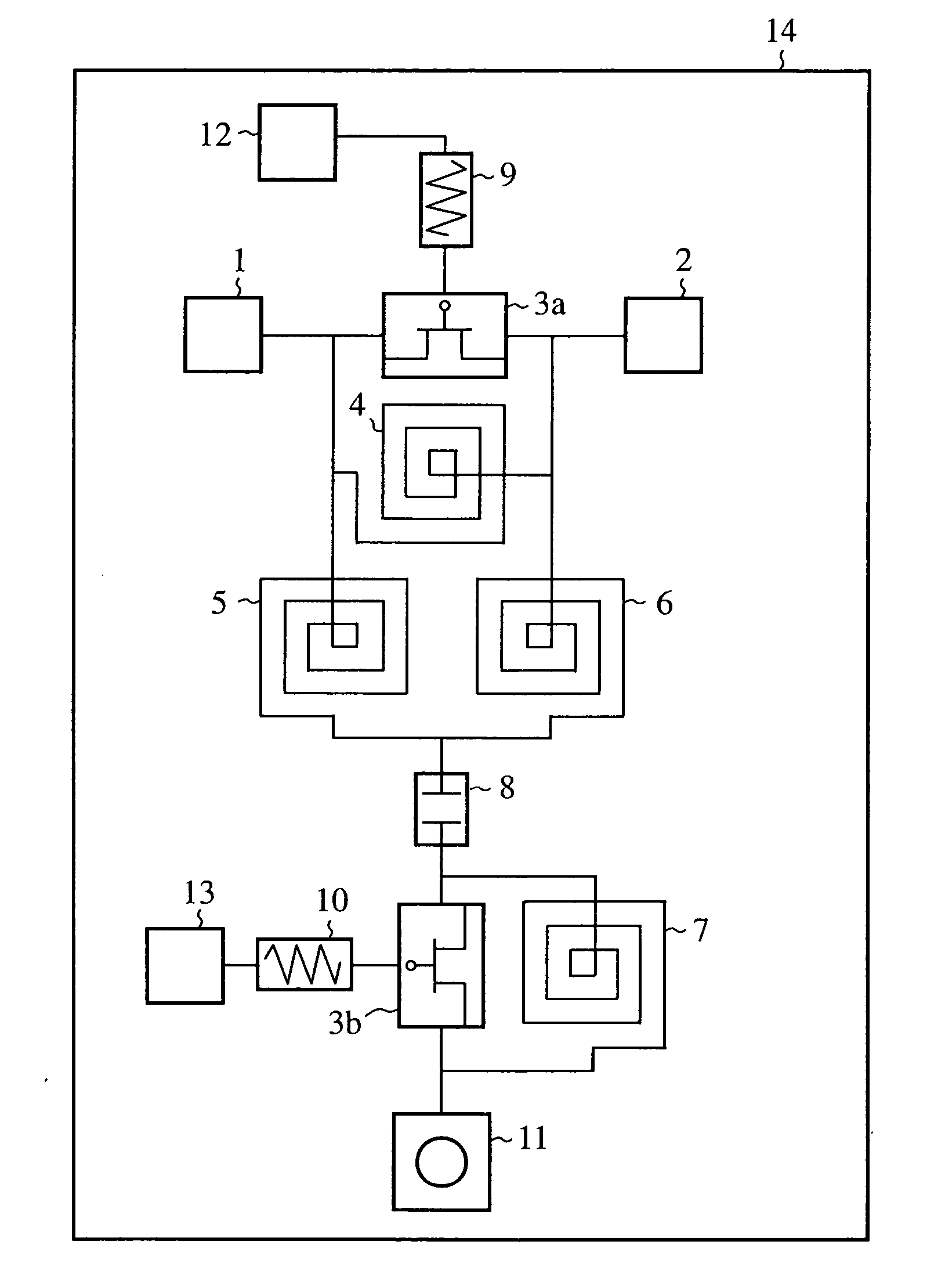
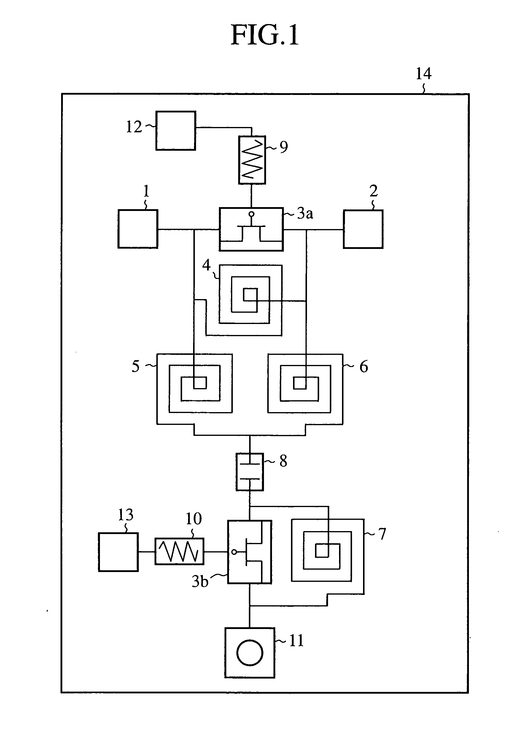
[0042]FIG. 1 is a circuit diagram showing a configuration of the phase-shifting circuit of an embodiment 1 in accordance with the present invention.
[0043] In FIG. 1, the phase-shifting circuit is formed monolithically on a semiconductor substrate 14. It is configured in such a manner that a parallel circuit (first parallel circuit) composed of an FET (first switching element) 3a and a spiral inductor (first inductor) 4 is connected across a high frequency signal input terminal 1 and an output terminal 2, and that the FET 3a has its gate supplied with a first control signal from an input terminal 12 via a resistor 9. In addition, a series circuit composed of a spiral inductor (second inductor) 5 and a spiral inductor (third inductor) 6 is also connected in parallel with the parallel circuit. The point of connection between the spiral inductor 5 and spiral inductor 6 is connected to a first terminal of an MIM capacitor 8. Between a second terminal of the MIM capacitor 8 and a through...
embodiment 2
[0052]FIG. 5 is a circuit diagram showing a configuration of the phase-shifting circuit of the embodiment 2 in accordance with the present invention. In FIG. 5, the same or like portions to those of FIG. 2 are designated by the same reference numerals, and duplicate explanation will be omitted basically. The configuration of the phase-shifting circuit includes an FET (third switching element) 25 in place of the capacitor 19 of FIG. 2.
[0053] The FET 25, which operates as a switch for switching the ON / OFF state, carries out the operation in the same manner as the FET 3a and FET 3b in response to the control signal.
[0054] Next, the operation will be described.
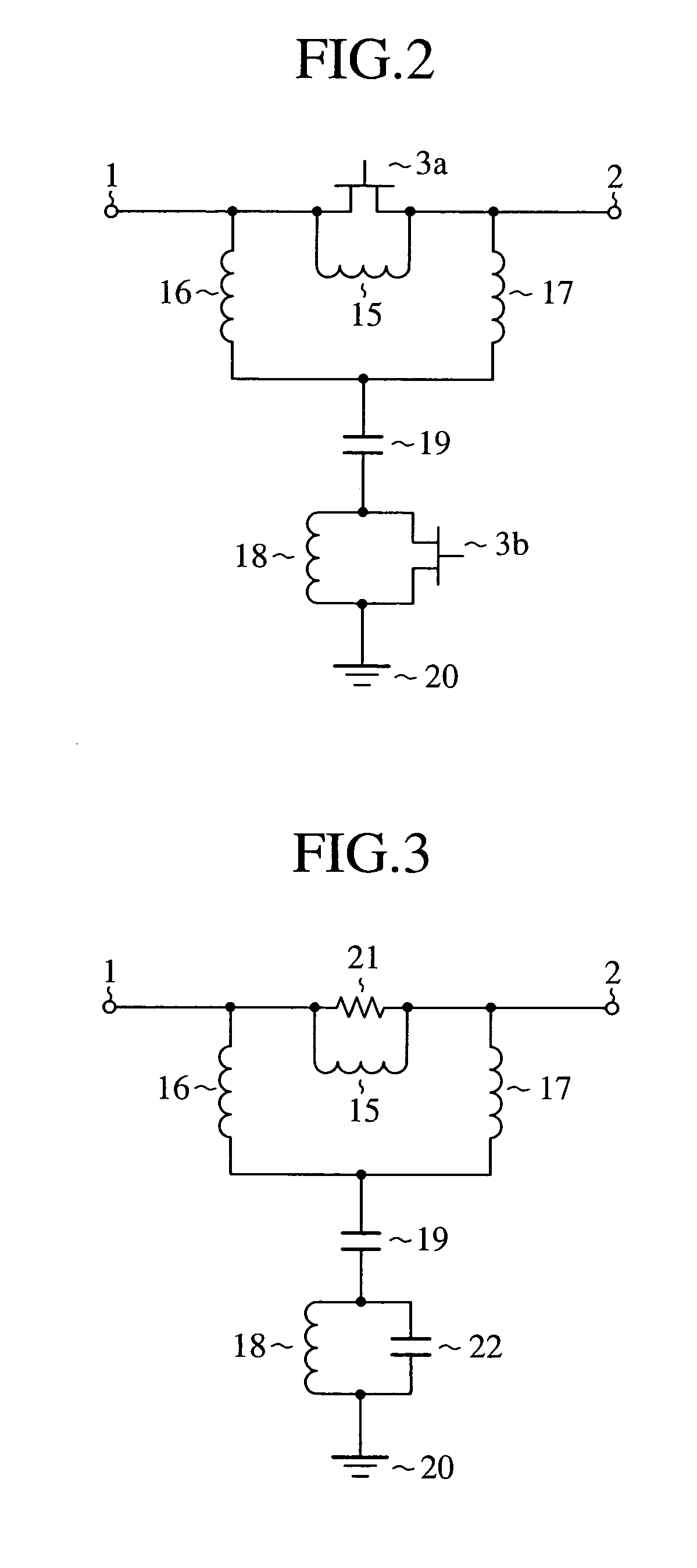
[0055] When the control signal sets the FET 3a at the ON state, the FET 3b at the OFF state and the FET 25 at the ON state, the phase-shifting circuit of FIG. 5 is considered to become the equivalent circuit as shown in FIG. 6. In FIG. 6, the same or like components to those of FIG. 3 are designated by the same reference numera...
embodiment 3
[0061]FIG. 8 is a circuit diagram showing a configuration of the phase-shifting circuit of an embodiment 3 in accordance with the present invention. In FIG. 8, the same or like portions to those of FIG. 2 are designated by the same reference numerals, and duplicate explanation will be omitted basically. The configuration of the phase-shifting circuit replaces the parallel circuit composed of the inductor 18 and FET 3b of FIG. 2 by only the FET 3b (second switching element).
[0062] Next, the operation will be described.
[0063] When the control signal sets the FET 3a at the ON state and the FET 3b at the OFF state, the phase-shifting circuit of FIG. 8 can be considered to have an equivalent circuit as shown in FIG. 9. In FIG. 9, the same or like components to those of FIG. 3 are designated by the same reference numerals.
[0064] In the circuit of FIG. 9, the combined capacitance of the capacitor 19 and OFF capacitance 22 is set in such a manner to become nearly an open state. Here, sin...
PUM
 Abstract
Description
Claims
Application Information
 - R&D
- Intellectual Property
- Life Sciences
- Materials
- Tech Scout
- Unparalleled Data Quality
- Higher Quality Content
- 60% Fewer Hallucinations
Browse by: Latest US Patents, China's latest patents, Technical Efficacy Thesaurus, Application Domain, Technology Topic, Popular Technical Reports.
© 2025 PatSnap. All rights reserved.Legal|Privacy policy|Modern Slavery Act Transparency Statement|Sitemap|About US| Contact US: help@patsnap.com


