
Multifunctional instrument introducer

a multi-functional, introducer technology, applied in the field of multi-functional devices, can solve the problems of not being able to support the use of vacuum, not being able to structurally stand alone, and not being able to achieve the effect of locating access sites in particular,

Inactive Publication Date: 2007-11-22
APONOS INC +1
View PDF24 Cites 117 Cited by
  • Summary
  • Abstract
  • Description
  • Claims
  • Application Information

AI Technical Summary

Benefits of technology

[0027]It is an object of this invention to provide a multifunctional instrument introducer which will allow the passage of endoscopic instruments through a large unobstructed central axial channel (“central channel”) into a body cavity, to and beyond a surgical access site located within said body cavity.
[0033]It is an object of this invention to provide a flexible introducer, optionally with endoscopic features, which can be provided in a sterile condition and maintain sterility in its internal channels and central lumen during navigation to a site internal of the body and execution of a procedure.
[0035]It is also an object of this invention to define a unique low-cost method of constructing a flexible tube multifunctional instrument introducer with the ability to be introduced into the body cavity atraumatically, further comprising one or more of an endoscope and an on-board optical guidance system.

Problems solved by technology

Such delivery devices are not especially efficacious for locating an access site, securing the site, maintaining a sterile field during the procedure, and effectively closing the incision upon leaving the surgical site.
However, it is limited in other desired capabilities.
It cannot structurally stand alone, nor support the use of vacuum.
Since it is a sheath, it has no structural strength along its axial length other than what the endoscope instrument provides.
This is a disadvantage in that a structural channel cannot be maintained without the endoscope, therefore the exchange of instruments within the sheath is not possible, nor is passing the endoscope beyond the tip element of the sheath based system also unattainable.
A multifunction al delivery system based on such an approach would severely limit the size of the instruments that could be passed within the central portion, because of the requirements for securing the interacting pivot like elements.
Such constructs are deficient in performance in passing instruments through the wall when locked, for if instruments were to be delivered within the structural walls of these embodiments, the peripheral axial path defined by the walls can become pinched and closed as the element interface surfaces are flexed and moved slideably by each other.
Furthermore, efforts to mitigate such pinching effect by removing material to clear away the pinching and high friction interference portion of the slideable surfaces then reduces the annular structural robustness, resistance to slippage and collapse resistance of the assembly, which must by design sustain a significant compressive force placed on each element by the locking members to attain the rigidity for transmitting torque in the locked state.
Thus, the prior art does not provide a highly torqueable introducer endoscopic instrument which does not rely on friction between slideable surfaces to provide torqueability.
Moreover, the prior art does not provide a torqueable introducer endoscopic instrument which provides useable passages in its walls for passage of control wires and other devices through its walls, in addition to passage through a central lumen.
The prior art also does not describe a highly torqueable introducer endoscopic instrument in which sterility can be maintained in the central lumen during deployment to, and use at, a site internal to the body.

Method used


Image

  • Multifunctional instrument introducer
  • Multifunctional instrument introducer
  • Multifunctional instrument introducer

Examples


Embodiment Construction

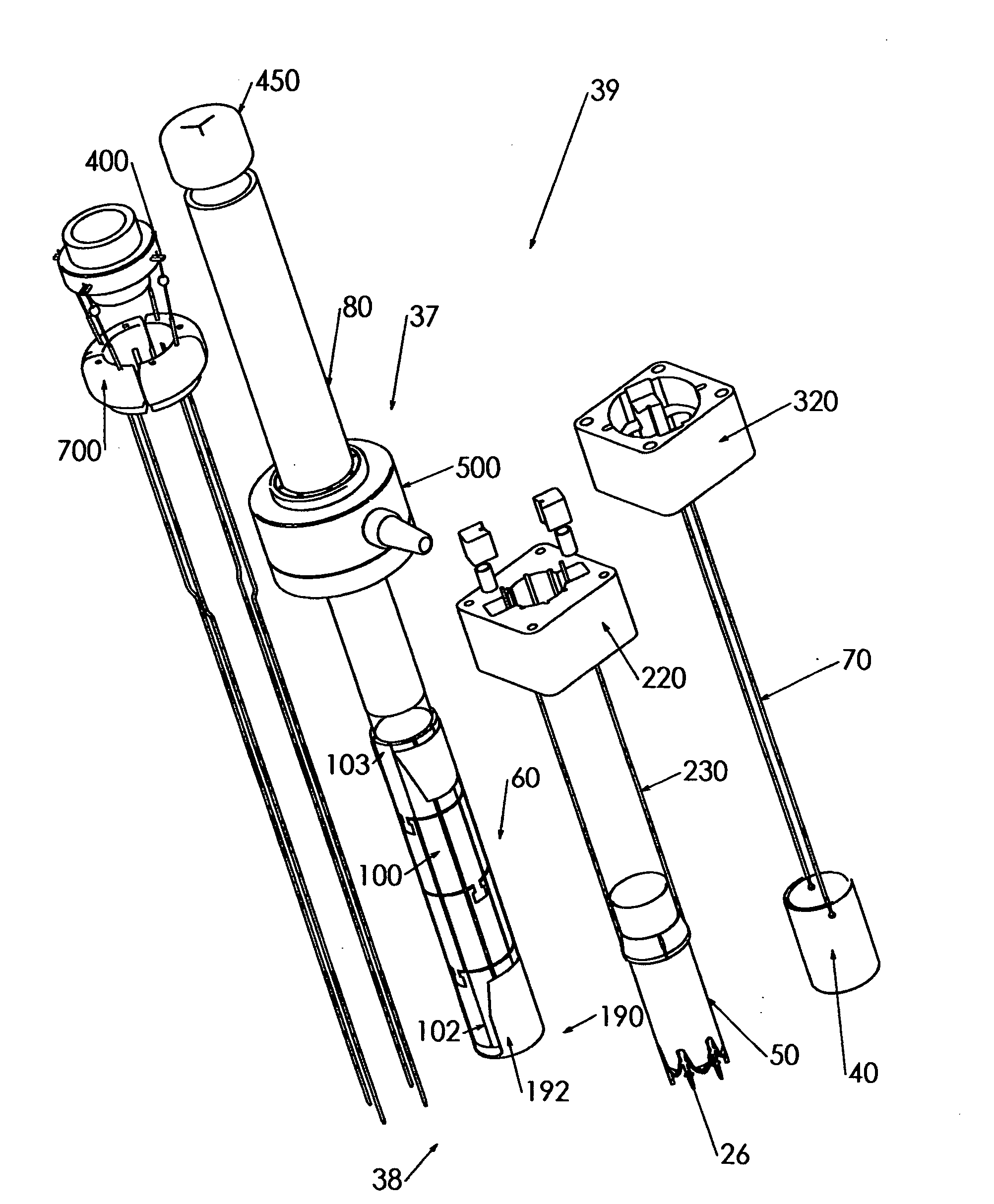
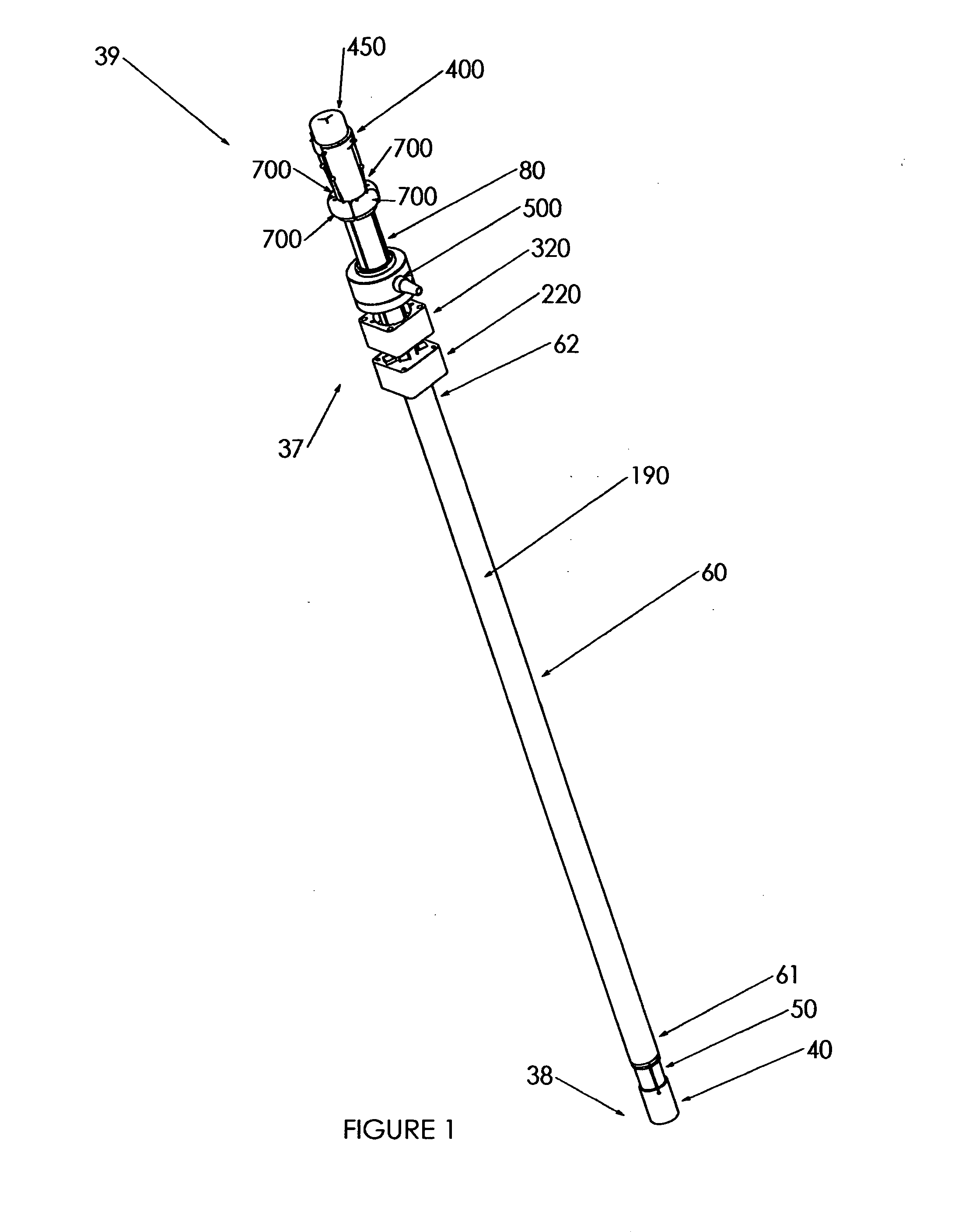
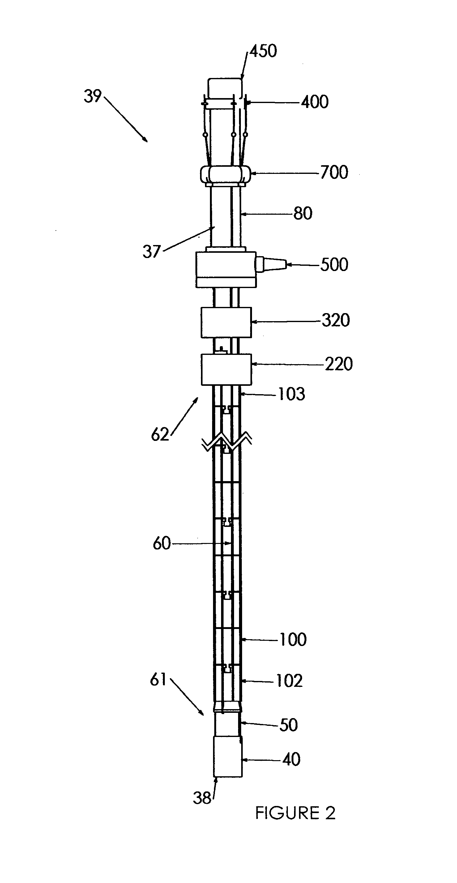
[0046]FIG. 1 shows an isometric view of the multifunctional instrument introducer in the preferred embodiment of the present invention. Referring to FIG. 1, multifunctional instrument introducer 39 is comprised of a multifunctional instrument introducer distal end detail 38, a multifunctional instrument introducer control end 37, and an endoscope delivery tube assembly 60 shown in this view as covered by outer sheath 190, and comprised of an endoscope delivery tube assembly distal end 61 and an endoscope delivery tube assembly proximal end 62. On the multifunctional instrument introducer 39, shell element 40 slides in a sealable manner on tubular connecting element 50 which is sealably engaged with endoscope delivery tube assembly distal end 61. Residing within shell 40 and not shown here is a self closing tissue fastener, intended for delivery by the introducer 39. Optionally, more than one tissue fastener could be carried in this manner.

[0047]Endoscope delivery tube assembly proxi...


PUM


Abstract

A flexible instrument introducer has a central channel and several peripheral channels in its outer wall for passage of instruments and other devices. It is assembled from three or more cylindrical elements, snapped together to give a limited degree of bending at each joint. The bending is confined to one or a few planes. The tube formed from the cylinders is stabilized and sealed by a flexible tube surrounding it, and said flexible tube confines controls and devices placed in the peripheral channels. The flexible tube also permits the maintenance of sterility and / or application of vacuum in the central and peripheral channels. The introducer may have an adaptor which keeps the distance from the proximal end to a device constant while the overall introducer bends.

Description

PRIORITY[0001]This application claims the benefit of the priority of U.S. provisional application 60 / 801,301, filed May 18, 2006, which is hereby incorporated in its entirety by reference where permitted.FIELD OF THE INVENTION[0002]The present invention relates to a multifunction device for introducing endoscopic devices and other surgical instruments into the body cavity, and, more particularly, to the design of a multi-lumen highly torque-able yet flexible device which can guide an endoscope or surgical instrument to target tissue within the body. This device includes multiple working channels formed in the wall of the device, and a clear, unobstructed, central axial channel which is capable of providing passage of one or more instruments to an internal site. The working channels can also be used to secure the device to a tissue wall. A sterile field may be provided within the central channel. Other devices, such as a tissue closure device, and be pre-positioned on the device. The...

Claims


Application Information

Patent Timeline
Patent Type & Authority Applications(United States)
IPC IPC(8): A61M5/178
CPCA61B1/00154A61B1/0057A61B17/34A61B17/3421A61B2017/003A61B2017/00637A61B2017/3443A61B2017/3445A61B2017/3484A61B2017/00278A61B2017/00314A61B2017/00323A61B2017/3488A61B1/00087A61B1/313
Inventor LABOMBARD, DENIS
Owner APONOS INC
Learn More