
Welding Electrode and Device for Its Manufacture

a technology of welding electrodes and manufacturing devices, which is applied in the direction of welding/cutting media/materials, manufacturing tools, welding apparatus, etc., can solve the problems of economic losses and breakdown of manufacturing processes, and achieve the effect of increasing the number of flawed recesses and facilitating the distribution of wires

Inactive Publication Date: 2007-11-22
ESAB AB
View PDF12 Cites 7 Cited by
  • Summary
  • Abstract
  • Description
  • Claims
  • Application Information

AI Technical Summary

Benefits of technology

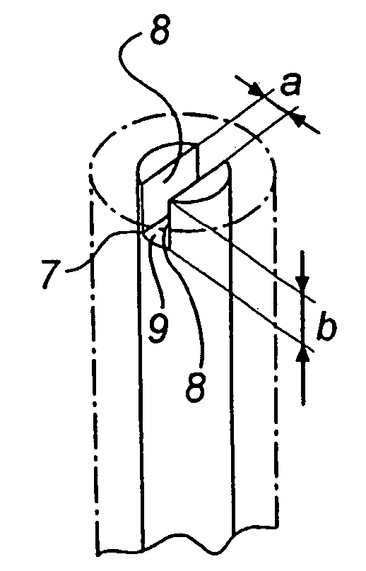
[0008] The present invention relates to a welding electrode for use in manual arc-welding operations, said electrode comprising a core wire having an arc ignition portion including an arc ignition face, the cross-sectional area of said arc ignition portion being reduced relative to the main cross section of the core wire. The arc ignition portion is formed with at least one recess the mouth of which opens in the longitudinal lateral face of the core wire. One consequence of forming a welding electrode with such a recess in its arc ignition portion is that the amount of material in said arc ignition portion will be reduced in comparison with the amount of material normally found in the cross section. The reduction of material in the core wire results in an increase of the electrical current intensity in the arc ignition portion compared with the case in a standard welding electrode, and consequently it provides the sought-after advantages, viz. increased probability of immediate arc starting, a more stable and therefore more controllable direction of the arc and increased development of heat at the moment of arc start-up, ensuring that the transition to the previously deposited weld seam / weld becomes as even and as faultless as possible. All these properties are particularly desirable for example in welding operations carried out on pipelines, where the welding conditions could be most difficult.
[0036] Finally, when the core wires are conveyed in, horizontal relationship through the device it may be advantageous to design the holding means, which also serves as a conveyor means, with a wedge-shaped profile configuration, in which wedge-shaped spaces the core wires may be supported during their transportation and the forming of the recess. The wedge-like shape makes each one of the circular core wires fall one by one into such a wedge space, separated from each other. This arrangement facilitates the distribution of wires in the holding means, preventing two core wires from being received in the same wedge, which on the one hand could damage the device and on the other increase the number of flawed recesses. In addition, the same holding means could be used for the manufacture of different wire dimension, i.e. core wires having different diameters. The process of positioning the core wires relative to the equipment designed to form the recess is effected by the very slitting means. In this case, the wedge shape prevents the core wires from getting stuck in the holding means and instead they may be lifted off the latter in a simple manner.

Problems solved by technology

In both cases, the result may be breakdown of the manufacturing process and in consequence thereof economical losses.

Method used


Image

  • Welding Electrode and Device for Its Manufacture
  • Welding Electrode and Device for Its Manufacture
  • Welding Electrode and Device for Its Manufacture

Examples


Embodiment Construction

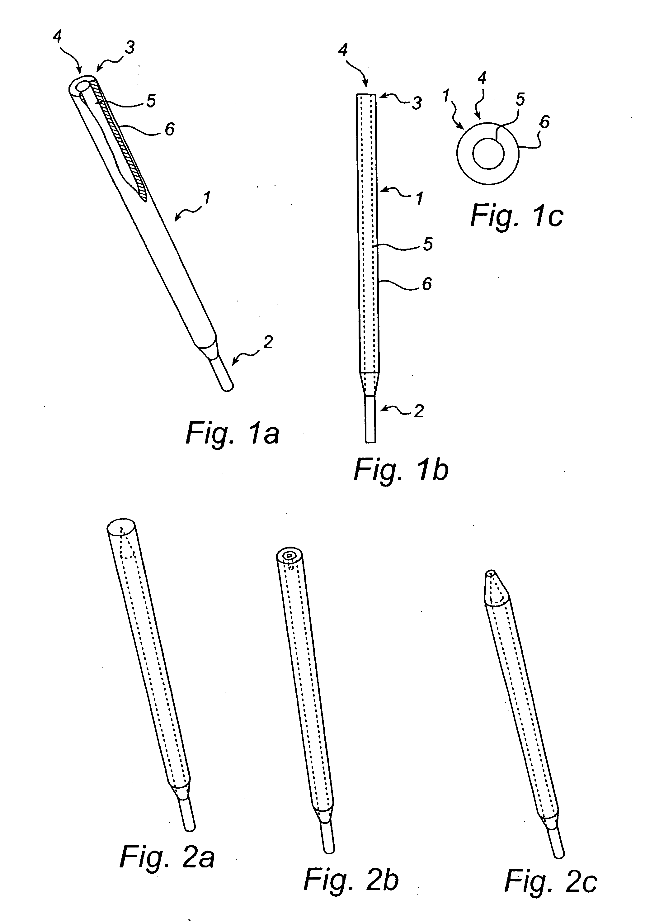
[0058]FIG. 1a shows a conventional welding electrode 1 in accordance with prior-art technology. The welding electrode 1 has a cylindrical core wire 5, enclosed by a sheath 6. The core wire 5 may consist of metallic materials of various types, depending on the intended use. In turn, the sheath 6 is made from a sheathing material that is transformed, during the welding operation, into slag, shielding gas and in some cases alloys, and serves to shield the weld metal of the core wire 5 from the surrounding atmosphere. In the manufacture of the welding electrode 1 the sheath 6 is applied in paste form, which is later heated and dried. Before the drying, an ignition face 4 is brushed clean of sheathing material in order to be able to ignite in welding. Also a holder part 2, located at the opposite end of the welding electrode 1, is brushed clean of sheathing material in order to create satisfactory contact with a holder (not shown) that transfers electric current to the welding electrode ...


PUM

PropertyMeasurementUnit
diameteraaaaaaaaaa
diameteraaaaaaaaaa
angleaaaaaaaaaa

Abstract

The present invention relates to a welding electrode (1) for use in manual arc-welding operations. The welding electrode comprises a core wire having an arc ignition portion including an arc ignition face, the cross-sectional area of said arc ignition portion being reduced relative to the main cross section of the core wire. The arc ignition portion is formed with at least one recess the mouth of which opens in the longitudinal lateral face of the core wire. The invention likewise concerns a device in the manufacture of welding electrodes for use in manual metallic arc welding operations. The manufacturing process comprises a unit for the manufacture of core wires and a unit for applying on said core wires a material forming slag and a shielding gas during the welding operation. The device has at least one shaping unit formed with at least one slitting means for forming at least one slit in one of the end portions of said core wires. It also has at least one holding means, in which said core wires are arranged to be collected in order to be advanced sequentially past the slitting means.

Description

TECHNICAL FIELD OF INVENTION [0001] The present invention relates to a welding electrode for manual metallic arc welding operations, said electrode comprising an arc ignition portion including an arc ignition face. The cross-sectional area of the arc ignition portion is reduced relative to the main cross-sectional area of the welding electrode. In addition, the present invention relates to a device in the manufacture of welding electrodes for manual metallic arc welding, said manufacturing process comprising a unit for the manufacture of core wires for welding electrodes and a unit for deposing and drying materials forming slag and shielding gas on the electrode core wires. BACKGROUND OF THE INVENTION [0002] Welding operations according to most welding methods require high temperatures in order to enable two metal pieces to be united. According to the oldest method, manual metallic arc welding, the source of heat is an electric arc the electric energy of which is transformed into th...

Claims


Application Information

Patent Timeline
Patent Type & Authority Applications(United States)
IPC IPC(8): B23K9/24B23K35/02B23K35/04B23K35/40
CPCB23K35/404B23K35/0261B23K35/365B23K9/32
Inventor OSKARSSON, PER-OVENORDELOF, ULFSANTESSON, OSKARSTROMHAGE, STAFFAN
Owner ESAB AB
Learn More