
Apparatus and Method for a Combination of Ablative and Nonablative Dermatological Treatment

Inactive Publication Date: 2007-11-15
RELIANT TECH INC
View PDF47 Cites 45 Cited by
  • Summary
  • Abstract
  • Description
  • Claims
  • Application Information

AI Technical Summary

Benefits of technology

[0012]In one aspect of the inventive method, discrete holes in epidermal and dermal tissue are patterned in the skin using optical energy. Nonablative energy is delivered from an optical source into at least two of the holes in the pattern. In one aspect, rapid healing of the treated tissue is promoted by treating the tissue fractionally.
[0014]The evaluation step may comprise the measurement of at least one characteristic of a portion of the ablated tissue. For example, the ablation rate, optical scattering properties, optical absorption properties, fluorescent emission properties, or a combination thereof can be measured. Multiple illumination or detection wavelengths can be used to improve the sensitivity and selectivity of optical measurements. In some embodiments, the nonablative treatment pulse is delivered into one or more holes created during the ablation step. In some embodiments, the majority of the optical energy in the nonablative treatment pulse does not extend beyond the edge of the holes created during the ablation step.
[0026]The surface of the selected region may be cooled in some embodiments to spare the epidermis or reduce side effects.

Problems solved by technology

Treating such large lipid-rich targets usually means using long thermal time constants and depositing large amounts of treatment energy in the skin.
The large amount of energy required for effective treatment causes side effects.
This approach requires messy carbon particles to be deposited on the skin, has limited efficacy due to limited penetration of particles into the desired treatment areas, and only addresses targets that are open at the surface to allow penetration by the absorbing particles.
Plugged targets, such as clogged pores, may not be treated because the absorbing particles cannot penetrate beyond the clogged opening.
Even using the selected wavelengths, overtreatment and undertreatment are problems due to the lack of feedback and spatial selectivity with the delivered energy.
's approach generally does not allow the delivery of nonablative treatment energy to lipid-rich targets while reducing optical absorption and / or the optical scattering of the tissue overlying the lipid-rich targets.
However, the creation of ablative holes or nonablative treatment zones alone is not an optimal treatment for lipid rich tissue that underlies a thick layer of absorbing and scattering tissue.
's approach generally does not allow the delivery of nonablative treatment energy to lipid-rich targets while reducing optical absorption and / or the optical scattering of the tissue overlying the lipid-rich targets.
However, ablative treatment alone typically will not optimally treat large buried targets because the size of the ablative holes will be larger than desired, which can increase the incidence of infection and scarring.

Method used


Image

  • Apparatus and Method for a Combination of Ablative and Nonablative Dermatological Treatment
  • Apparatus and Method for a Combination of Ablative and Nonablative Dermatological Treatment
  • Apparatus and Method for a Combination of Ablative and Nonablative Dermatological Treatment

Examples


Embodiment Construction

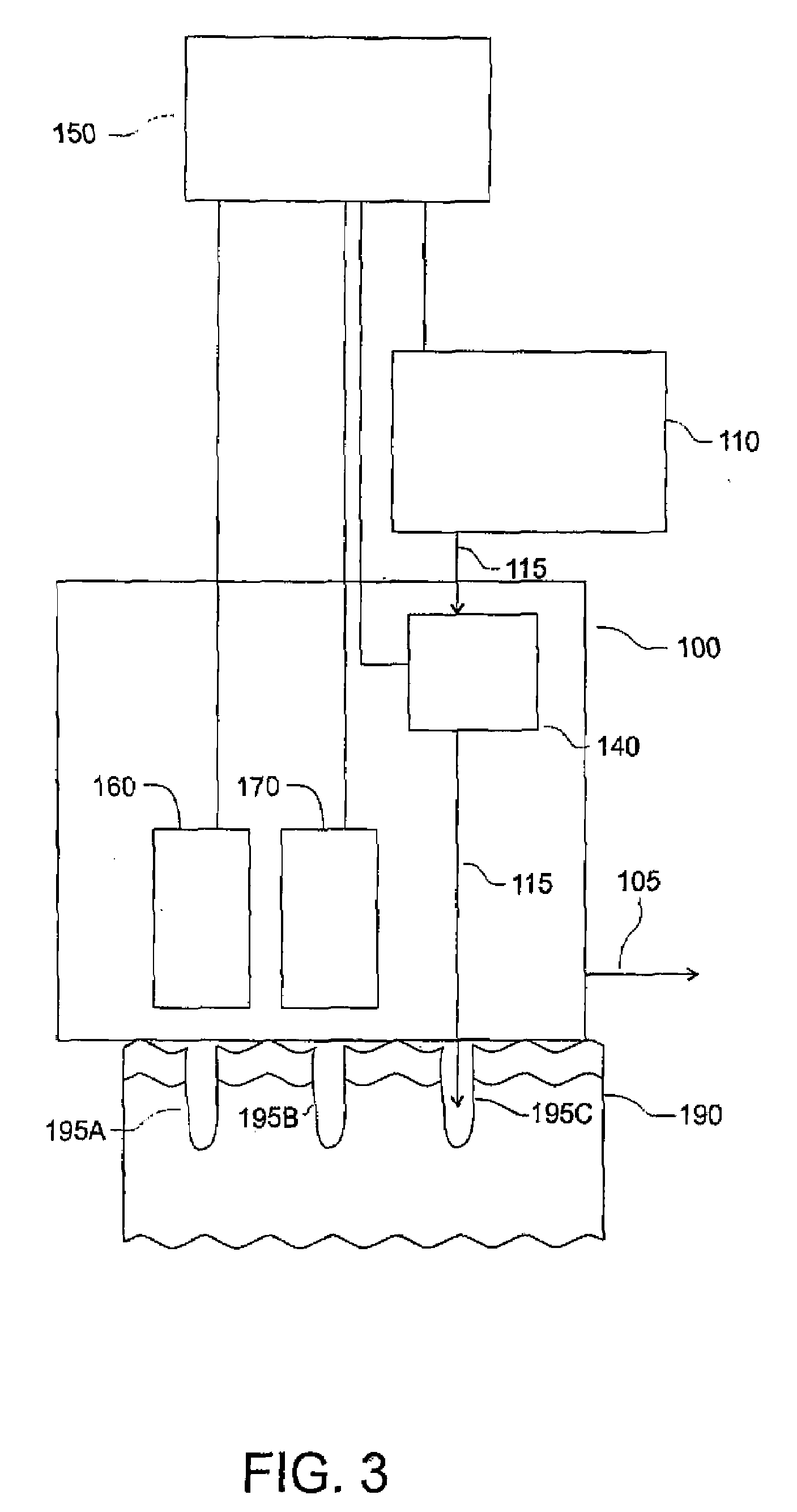
[0036]The example inventive system illustrated in FIG. 3 includes a controller 150 that controls an optical source 110 that emits one or more pulses of optical energy 115. A delivery system 140 is configured to receive and direct the optical energy 115 from the optical source 110 to a target region of skin 190 to create holes 195 in the skin 190. The system further comprises an optional positional sensor 160 and an optional sensing element 170 that each provide feedback to the controller 150. The optical energy 115 that is delivered to the skin 190 can be adjusted or triggered by the controller 150 in response to signals received from the positional sensor 160, the sensing element 170, or a combination thereof. Alternatively, the controller 150 can be preprogrammed to deposit a particular pattern of energy without feedback from either a sensing element 170 or a positional sensor 160. The controller 150 can control the treatment by adjusting parameters of the optical source 110, the ...


PUM


Abstract

The invention describes a treatment for skin wherein a pattern of holes is ablated in a selected region of skin tissue using an optical source. Substantially nonablative energy is delivered to the selected region to at least two holes in the pattern to thermally heat a target in or just beneath the skin, such as hair follicles, sebaceous glands, or subcutaneous fat. The invention may further be improved by adding a feedback mechanism that adapts the nonablative energy in response to a measurement enabled by the ablation of holes. The apparatus may include a positional sensor to provide additional dosage control, particularly when the inventive method is used with a continuously movable handpiece.

Description

CROSS-REFERENCE TO RELATED APPLICATION(S)[0001]This application claims priority under 35 U.S.C. § 119(e) to U.S. Provisional Patent Application Ser. No. 60 / 800,144, “Apparatus and Method for a Combination of Ablative and Nonablative Dermatological Treatment,” filed May 11, 2006, which is incorporated by reference herein in its entirety.BACKGROUND OF THE INVENTION[0002]1. Field of the Invention[0003]This invention relates generally to a dermatological treatment of skin using ablative and nonablative optical treatment energy. More particularly, it relates to a method and apparatus for delivering nonablative energy into tissue that has been ablated to create a pattern of holes in the skin.[0004]2. Description of the Related Art[0005]Lipid-rich tissues and regions are common targets for dermatological treatments. Examples of lipid-rich targets are sebaceous glands, sebaceous cysts, and subcutaneous fat. Each of these targets is typically large and can be larger than 1 mm in diameter. Tr...

Claims


Application Information

Patent Timeline
IPC IPC(8): C12Q1/00A61N5/067
CPCA61B18/20A61B18/203A61B2017/00061A61B2017/00106A61B2018/00452A61N5/0616A61B2018/00642A61B2018/00904A61B2018/207A61B2018/2085A61B2018/00458A61B2018/20351A61B2018/20554
Inventor DEBENEDICTIS, LEONARD C.FRANGINEAS, GEORGE
Owner RELIANT TECH INC
Learn More