Image forming apparatus
- Summary
- Abstract
- Description
- Claims
- Application Information
AI Technical Summary
Benefits of technology
Problems solved by technology
Method used
Image


Examples
first embodiment
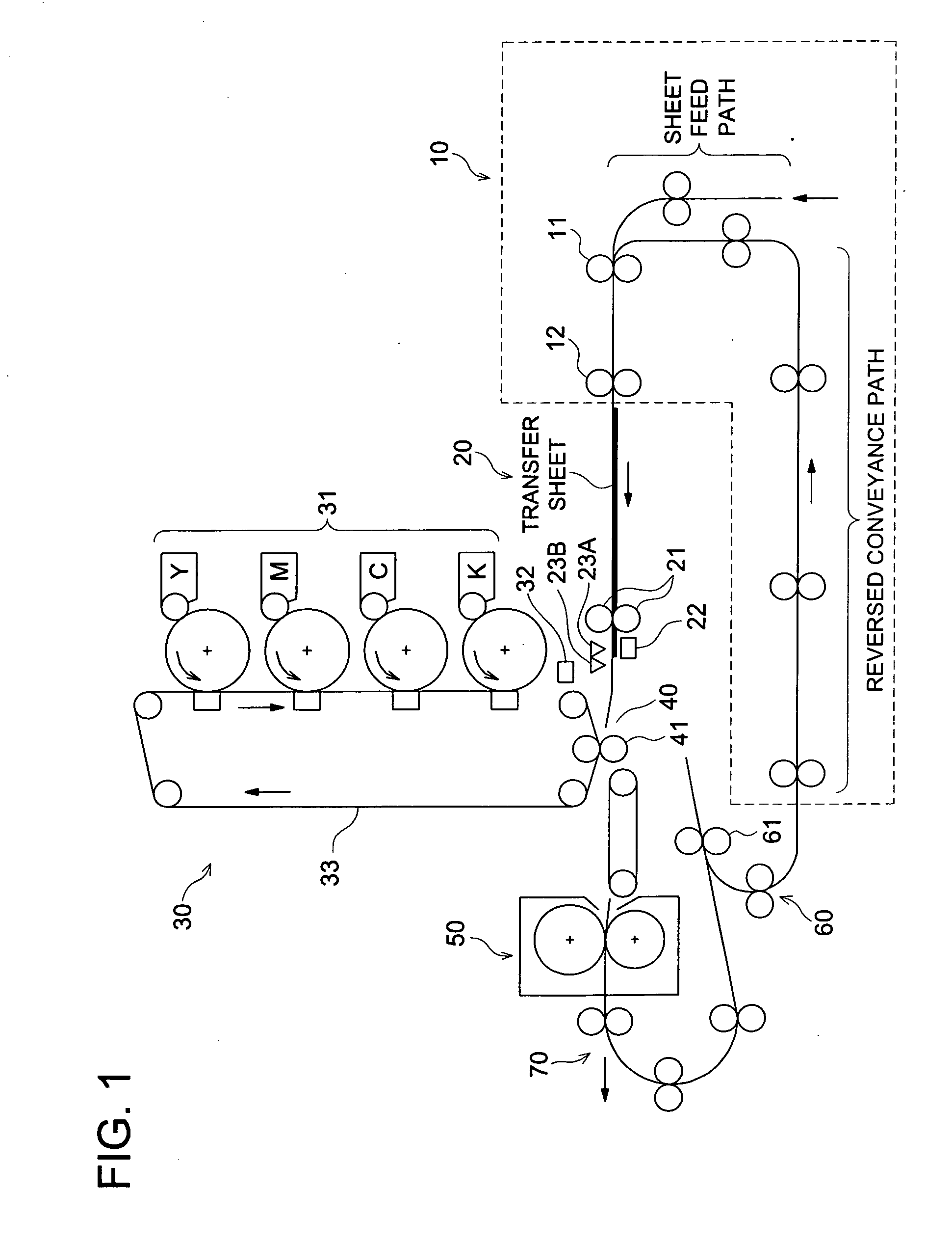
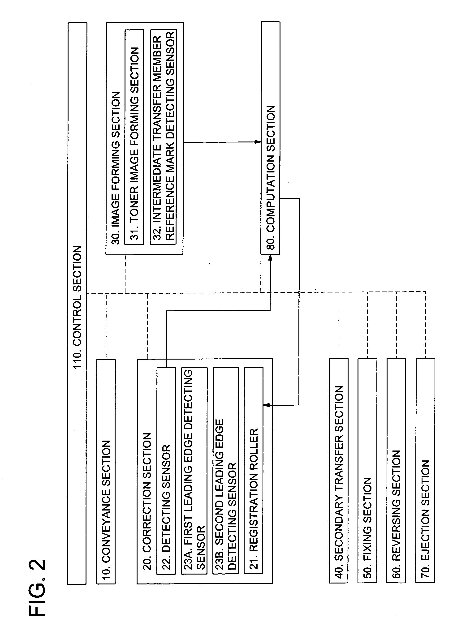
[0030]FIG. 1 is a schematic diagram schematically representing the conveyance path of an image forming apparatus as an embodiment of the present invention. FIG. 2 is a block diagram representing the structure of the image forming apparatus as a first embodiment of the present invention. FIG. 3 is a drawing representing the operation of the image forming apparatus as an embodiment of the present invention. FIG. 4 is a flow chart showing the control of correcting the position across the width of the transfer sheet in an embodiment of the present invention.
[0031]The image forming apparatus of the present embodiment contains a sheet conveyance section 10, correcting section 20, image forming section 30, secondary transfer section 40, fixing section 50, reversing section 60, and sheet ejection section 70, as shown in FIG. 1. These sections are placed under the control of a control section 110, as shown in FIG. 2. The solid line of FIG. 2 indicates the flow of information, while the dotte...
second embodiment
[0065]The first embodiment is intended to provide correction across the width when an image is transferred onto the rear surface of the transfer sheet P. The second embodiment provides correction across the width when an image is transferred onto both the front and rear surfaces of the transfer sheet P.
[0066]The structure of the image forming apparatus as the second embodiment is almost the same as that of the first embodiment. In the first embodiment, the transfer sheet reference mark A12 is used to check the position of the transfer sheet P across the width; whereas in the second embodiment, the detecting sensor 22 detects the position of the edge on one side of the transfer sheet P with respect to the center as the reference position. This detecting sensor 22 corresponds to the “sheet edge position detecting section” of this invention. As shown in FIG. 5, the further difference from the first embodiment is that the second embodiment includes the sheet width information acquisitio...
third embodiment
[0094]The structure of the image forming apparatus as a third embodiment is basically the same as that of the first and second embodiments. The difference is that the detecting sensor 22 of the third embodiment performs the functions of detecting both the sheet edge position and the transfer sheet reference mark on transfer sheet, and the third embodiment is provided with a detecting section that detects the position of the edge on one side of the transfer sheet only when the transfer sheet reference mark A12 on the transfer sheet is not detected.
[0095]The following describes the image formation flow of the present embodiment with reference to FIG. 8. Here, the S-number refers to the step number of FIG. 4 and FIG. 7.
[0096](1) Transfer sheet P is fed from the sheet feed tray to the sheet conveyance section 10 (S201).
[0097](2) Transfer sheet P is fed out by the loop roller 11 and sheet feed roller 12 until it hits the registration roller 21 (S202).
[0098](3) The registration roller 21 ...
PUM
 Abstract
Description
Claims
Application Information
 - R&D
- Intellectual Property
- Life Sciences
- Materials
- Tech Scout
- Unparalleled Data Quality
- Higher Quality Content
- 60% Fewer Hallucinations
Browse by: Latest US Patents, China's latest patents, Technical Efficacy Thesaurus, Application Domain, Technology Topic, Popular Technical Reports.
© 2025 PatSnap. All rights reserved.Legal|Privacy policy|Modern Slavery Act Transparency Statement|Sitemap|About US| Contact US: help@patsnap.com