
Real-time nighttime vehicle detection and recognition system based on computer vision

a recognition system and vehicle technology, applied in scene recognition, instruments, computing, etc., can solve the problems of increasing the fatality of driving, the interference phenomenon of incoming vehicle drivers, and the cost of deployment of such type of equipment is rather high, so as to achieve high efficiency, high speed, and the effect of prime cost of the operating mechanism

Inactive Publication Date: 2007-11-15
CSSP
View PDF10 Cites 74 Cited by
  • Summary
  • Abstract
  • Description
  • Claims
  • Application Information

AI Technical Summary

Benefits of technology

[0006]With reference to the issue mentioned above, the present invention has brought up a perspective imaging model through CCD image retrieving technology and computer vision collocation to carry out night time incoming vehicle detection and determination of distance. The decision of the present invention is a high speed computer vision algorithm method, which can drastically reduce and accomplish the prime cost of the operating mechanism, at the same time possesses quite an extent of reliability, it is a solving proposal of high efficiency and low cost.
[0010]As fore-mentioned, the present invention of real time night time vehicle detection and identification system relies on a CCD video retrieving system installed at the back of the windshield, to accurately detect traffic conditions within the viewable range ahead of the vehicle, to identify vehicle head light of incoming vehicle on the opposing lane and vehicle tail lamp of preceding vehicle on the lane in concern and to determine and demarcate the relative positions and vehicle count of each preceding vehicle and incoming vehicle, so that the driver can be further assisted to determine traffic conditions and thus automatically controls the relative device (as for example switching of high beam and low beam of vehicle's head light).
[0017]As mentioned above the virtue possessed by the system and methods of the present invention includes: efficiently and accurately demarcate and detect the vehicle lighting of incoming vehicle and preceding vehicle on the road at all different conditions of night time road lighting, and accurately provides information to assist the driver in analyzing traffic conditions in front of the vehicle. During the detection and determination of traffic conditions on the preceding lane, when this night time vehicle detection and identification system is applied on the control of high and low beam light then it can automatically adjust the high beam light and the low beam light of the vehicle's head light to the most optimum condition, if vehicles is detected then it is switched to low beam light to prevent the reflection from affecting the drivers of incoming vehicles ahead, it is to prevent distractions caused by dizziness due to illumination of high beam light of incoming vehicle at a short range which can result in dangers of traffic accident; when there is already no vehicles on the lane ahead, then it will send out control signals to switch back to high beam light so as to assist the driver to clearly catch sight of the road conditions on the far side.DETAILED DESCRIPTION OF PREFERRED EMBODIMENTS OF THE INVENTION
[0042]Due to illuminant object plane gained from previous bight object retrieving procedure, the illuminant body of non vehicle lighting object (as for example, streetlights, traffic lights, neon lights et cetera) is usually located at a point higher than the line of sight ahead. In order to eliminate the illuminant body of non vehicle lighting in advance, so as to speed up the processing speed, an imaginary horizon line is set up as shown in FIG. 6. The imaginary horizontal line is configured to one third of the retrieved image area, this line approximately coincides with the horizon line extending afar, the illuminant object below this line, if determined to be positioned on the road is mostly certain to be vehicle lighting, hence the processing efficiency is drastically increased.
[0062]By way of the above mentioned mathematical equations, the information about distance, relative velocity and relative lateral positions et cetera between the vehicle in concern and the preceding detected target vehicle on the lane can be gained, this way the driver can be assisted in learning about the information of relative positions and motion between the vehicle in concern and the preceding vehicle so as to adopt the correct corresponding operations and prevent night time vehicle accidents from happening, more further application of this detection information is to use it as an automated control mechanism of vehicle cruise velocity and driving route, so as to increase the safety of night time driving.

Problems solved by technology

Due to diverseness of road condition during night time, an average driver ought to rely on the use of high beam light or low beam light to make a decision, so as to gain road condition messages of varying distances, however, as for example if discovered there is incoming preceding vehicle in within a comparatively short distance, at this moment on similar use of high beam light, phenomenon of interference of incoming vehicle driver happens to occur.
Traditional vehicles system, because of its incapability to detect traffic conditions within a certain distance by itself, hence automatic switching from high beam light to low beam light all of a sudden, or switching the other way round, both causes dizziness in drivers of moving vehicle due to sudden illumination of light rays, increasing the fatalness of driving.
On the basis of the need mentioned above, namely, an operating mechanism which can automatically switch high beam low beam lights, for the time being there is already numerous technologies which can accomplish it, wherein vast majority of the systems adopts ultrasound or vehicle radar to accomplish the decision of incoming vehicle distance, however, the cost to deploy such type of equipment is rather high.
Nevertheless if photodiode et cetera is used, only can it determine the possibility whether vehicle exists ahead or not in accordance with whether the blaze appears or not, but because it is still unable to differentiate whether the light source is the lighting of a real vehicle or light source of other circumstances, as for example the intense scintillation of shop signs therefore it is likely to bring about phenomenon of erroneous decision.
Furthermore, because the technology uses fixed threshold values configured beforehand, it is unable to adaptively adjust the selection of threshold values aimed at different conditions of night time lighting, so when put in use in a circumstance where road condition have different lighting conditions, it is unable to maintain efficiency of absolute unanimity.

Method used


Image

  • Real-time nighttime vehicle detection and recognition system based on computer vision
  • Real-time nighttime vehicle detection and recognition system based on computer vision
  • Real-time nighttime vehicle detection and recognition system based on computer vision

Examples


Embodiment Construction

[0018]Further description of the present invention of real time night time vehicle detection and identification system and its method is done with the coordination of diagrams and implementations as follows.

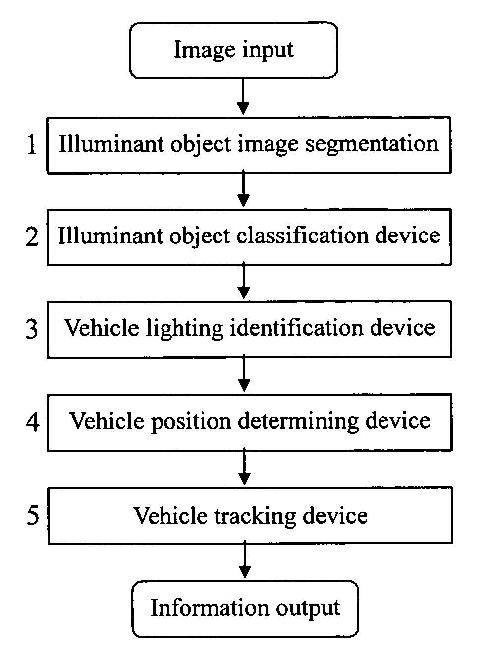
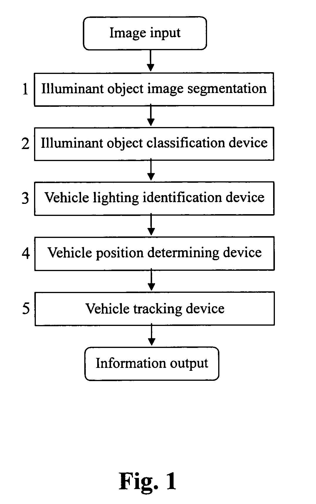
[0019]The present invention of real time night time vehicle detection and identification system is provided with the processing devices listed below: an illuminant object image segmentation device 1, an illuminant object classification device 2, a vehicle lighting object identification device 3, a vehicle position determining device 4 and a vehicle tracking device 5, its whole framework of mathematic operations is as shown in FIG. 1, the steps of mathematical calculations of each processing devices described in order is shown below.

[0020]First of all, video camera installed at the back of the windshield inside the vehicle shoots at the vehicle's front, during driving at night time, night time road condition images in front of the vehicle is retrieved through a video camera, as sh...


PUM


Abstract

The present invention relates to a real time night time vehicle detection and identification system comprising of an illuminant object image segmentation device 1, an illuminant object classifying device 2, a vehicle lighting object identification device 3, a vehicle position determining device 4 and a vehicle tracking device 5. Under various circumstances of road lighting during nighttime, the system can efficiently and accurately demarcate and identify the lamps of incoming and preceding vehicles and accurately provides the driver with auxiliary information needed to analyze the traffic conditions in front of the vehicle during the conditions met on the road at that time.

Description

CROSS-REFERENCES TO RELATED APPLICATION[0001]The present invention relates to an intelligent real time night time vehicle detection and identification system utilizing computer vision.BACKGROUND OF THE INVENTION[0002]During the course of night time driving, the driver ought to rely on the illumination of head light to learn about the condition of preceding vehicles, including traffic of incoming vehicle, relative position and distance, perception about the condition of incoming rear vehicles is also the same, it ought to rely on the incoming rear vehicle's head light and its illumination to determine it. Due to diverseness of road condition during night time, an average driver ought to rely on the use of high beam light or low beam light to make a decision, so as to gain road condition messages of varying distances, however, as for example if discovered there is incoming preceding vehicle in within a comparatively short distance, at this moment on similar use of high beam light, phe...

Claims


Application Information

Patent Timeline
IPC IPC(8): G06K9/00G06K9/62
CPCG06K9/00825G06K9/00805G06V20/58G06V20/584
Inventor WU, BING-FEICHEN, YEN-LINCHEN, YUAN-HSINCHEN, CHAO-JUNG
Owner CSSP
Learn More