
Nailer with adjustable guide member

Active Publication Date: 2007-11-08
LABE PRIMATECH
View PDF17 Cites 19 Cited by
  • Summary
  • Abstract
  • Description
  • Claims
  • Application Information

AI Technical Summary

Benefits of technology

[0029] In one embodiment, the nailer further comprises a security plunger blocking member selectively releasably engageable in said nail ejection channel to thus selectively prevent the movement of said plunger in said nail ejection channel for preventing accidental ejection of the nail out of said nail outlet.

Problems solved by technology

A problem with conventional nailers such as the one detailed hereinabove is that they are adapted to work with a very narrow range of hardwood flooring board types.
More specifically, in the prior art nailers, the position of the nail ejection channel relative to its sole and to its vertical abutment surface is fixed, and consequently these two elements that act to guide the user of the nailer into properly positioning the nailer before ejecting the nail, cannot accommodate wooden boards of different configuration.
Therefore, the nailers can only be used with a single wooden board type or at best with a narrow range of wooden board types.

Method used


Image

  • Nailer with adjustable guide member
  • Nailer with adjustable guide member
  • Nailer with adjustable guide member

Examples


Embodiment Construction

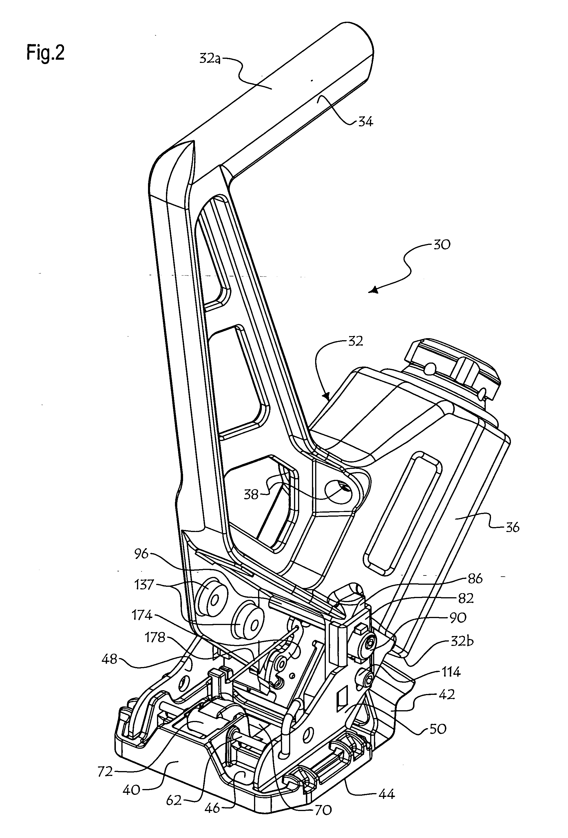
[0048] In the annexed drawings, FIGS. 1-3 show a pneumatic nailer 30 according to the present invention. It is understood that nailers with other alternate actuator means than the conventional pneumatic pressure could be used, although the following description will detail a pneumatic nailer.

[0049] Nailer 30 is destined to be used to nail wooden boards to a sub-floor (not shown) for forming a surface of hardwood flooring, although it is not limited to such a purpose. To this end, the user of nailer 30 will strike the head portion of nailer 30 as described hereinafter with a hammer, to activate the pneumatically pressurized nailer 30 that will drive a nail through a wooden board.

[0050] Nailer 30 comprises a main body 32 defining opposite upper and lower ends 32a, 32b and a longitudinal axis there between. Nailer 30 has a handle 34 at its upper end 32a and an actuation chamber 36. A pair of pressurized air inlet ports 38, 38 are provided on actuation chamber 36. Pneumatic air hoses ...


PUM

PropertyMeasurementUnit
Angleaaaaaaaaaa
Angleaaaaaaaaaa
Displacementaaaaaaaaaa

Abstract

The nailer comprises a main body, an elongated nail ejection channel in the main body for receiving a nail to be ejected and including a nail outlet leading out of the main body, and a plunger carried within and movable along the nail ejection channel. The nailer also includes an actuator capable of moving the plunger along an ejection axis in the nail ejection channel for selectively ejecting the nail out through the nail outlet. A first guide member is carried by and movable relative to the main body, for engaging a first reference surface outboard of the nailer, and a first adjuster mechanism capable of adjusting the position of the first guide member relative to the main body is also provided. The position of the nail ejection channel can be adjusted relative to the first reference surface with the first adjuster mechanism when the nailer engages the first reference surface with the first guide member.

Description

FIELD OF THE INVENTION [0001] The present invention relates to nailers, and more particularly to a nailer with one or more adjustable guide members allowing the position of the nailer's nail ejection channel to be adjusted relative to one or more reference surfaces located outboard of the nailer when the nailer engages the reference surfaces with corresponding guide members. BACKGROUND OF THE INVENTION [0002] Nailers are used to drive nails through different construction materials such as hardwood flooring. Pneumatic nailers are often used for this purpose, although there exist different types of nailers. Conventional pneumatic nailers are provided with a main body having an elongated nail ejection channel therein for receiving a nail from a nail magazine carried by the nailer main body. The nail is to be ejected more particularly through a nail outlet of the nail ejection channel leading out of the main body. A plunger carried within and movable along the nail ejection channel is a...

Claims


Application Information

Patent Timeline
IPC IPC(8): B25C7/00
CPCB25C1/008B25C7/00B25C1/041
Inventor DION, MARCLAVOIE, DAVIDMALTAIS, JACQUES
Owner LABE PRIMATECH
Learn More