Fluid dispenser head, a dispenser including such a head, and a method of manufacturing such a head

a technology of dispensers and heads, which is applied in the direction of engine diaphragms, diaphragm valves, instruments, etc., can solve the problems of inability to hold the head firmly, flexible hoses that do not always make it possible to effectively decouple the endpiece from the nozzle, and the end is not stable and firm enough to ensure the leakage tightness of the hose. , to achieve the effect of convenient moldability

Inactive Publication Date: 2007-11-08
VALOIS SA
View PDF17 Cites 13 Cited by
  • Summary
  • Abstract
  • Description
  • Claims
  • Application Information

AI Technical Summary

Benefits of technology

[0009]To do this, the present invention proposes that the flexible hose is injection-molded on at least one of the endpiece and the nozzle. The flexible hose advantageously includes two connection ends that are injection-molded respectively on the endpiece and on the nozzle. The flexible hose may thus be made of a material selected from the family of thermoplastic elastomers. Injection-molding makes it possible to use plastics materials that are more flexible, and that offer less rigidity. Injection-molding makes it possible to dispense of the rigidity requirements previously required in order to be able to hold the hose, and engage it on the endpiece and / or the nozzle. In addition, by using materials that are more flexible and less rigid, the hose can be completely or almost completely decoupled from the endpiece, while guaranteeing a good supply of fluid. The endpiece and the hose can thus be assembled with configurations and dispositions that would be impossible with a flexible hose that needs to be connected or fitted.
[0012]In another method of manufacturing a dispenser head as described above, the flexible hose is molded in rectilinear shape by using a rectilinear pin that passes through the endpiece and / or the nozzle, and the nozzle is then mounted in its support with the hose deforming. Whereas in the prior art it is necessary to engage both ends of the hose, with the invention it suffices to mount the nozzle on its support without having to worry about connecting the hose. The actuator means are advantageously molded in rectilinear shape, extending substantially perpendicularly to the hose. This makes it easier to mold the head as a single part.

Problems solved by technology

With a hose that is too flexible, it is not possible to hold it firmly without the risk of flattening it and of damaging it, and the engagement of the ends is not stable and firm enough to guarantee that the hose is leaktight relative to the endpiece and to the nozzle.
However, the relative rigidity of the flexible hose does not always make it possible to decouple the endpiece from the nozzle effectively.
In other words, the hose is often too rigid to accommodate the relative displacement between the endpiece and the nozzle.
The relative rigidity of the flexible hose is also a drawback even when the endpiece is not displaceable relative to the nozzle.
In this event, if the flexible hose is too rigid, it cannot be used to connect the endpiece to the nozzle.

Method used


Image

  • Fluid dispenser head, a dispenser including such a head, and a method of manufacturing such a head
  • Fluid dispenser head, a dispenser including such a head, and a method of manufacturing such a head
  • Fluid dispenser head, a dispenser including such a head, and a method of manufacturing such a head

Examples


first embodiment

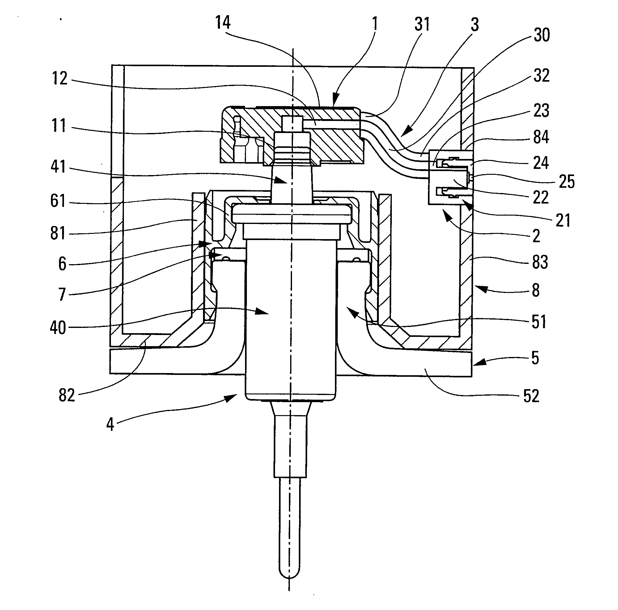
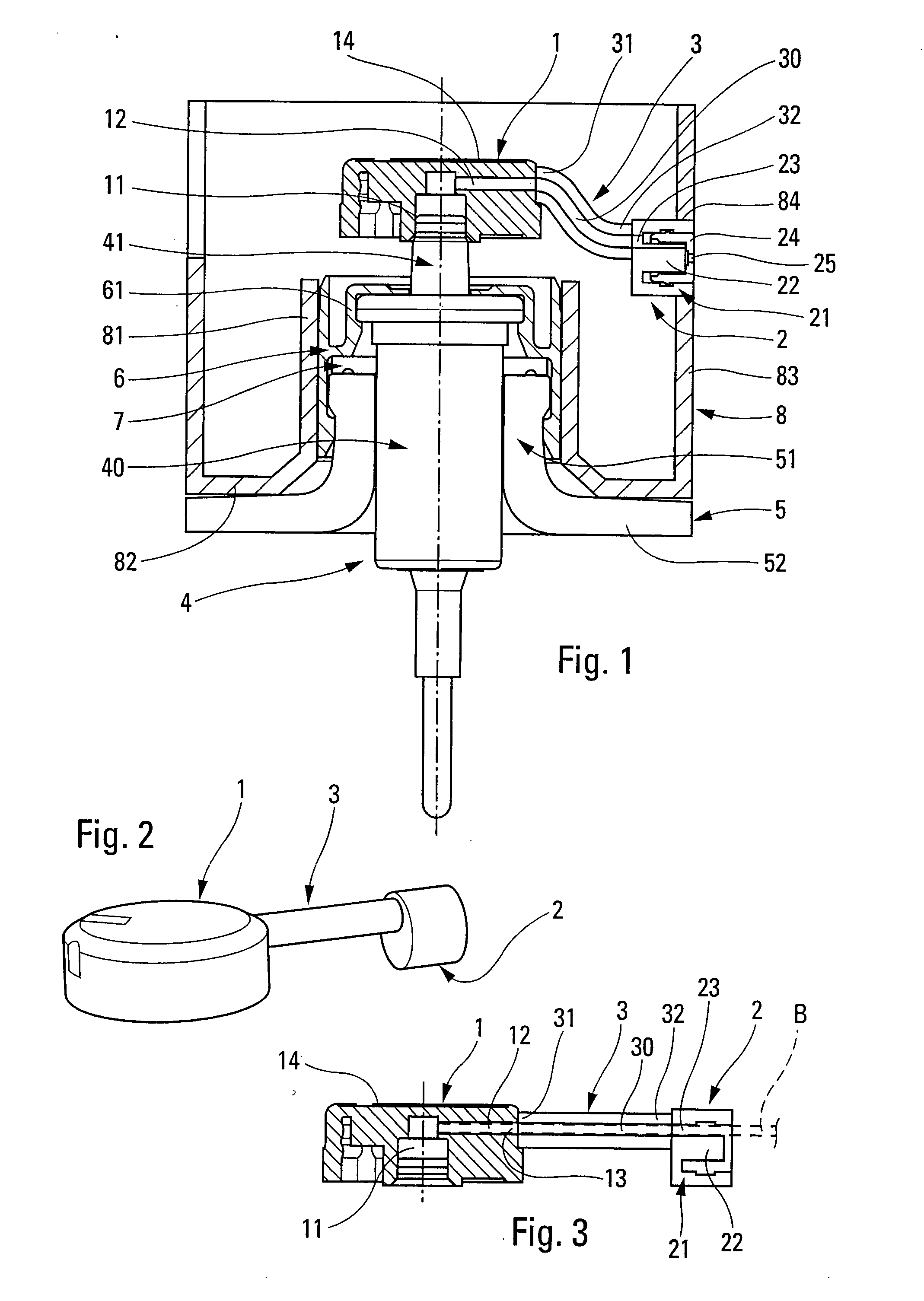
[0022]Reference is made firstly to FIGS. 1 to 3 in order to explain in detail the manufacture, the structure, and the functioning of the dispenser head of the In FIGS. 2 and 3, it can be seen that the dispenser head comprises three parts, namely an endpiece 1, a nozzle 2, and a flexible connection hose 3.

[0023]The endpiece 1 can be made by injection-molding a plastics material that is relatively or substantially rigid. The endpiece 1 forms a connection sleeve 11 for force fitting on the outlet from a dispenser member, such as a pump or a valve, as described below. The endpiece 1 also includes an internal channel 12 that puts the sleeve 11 into communication with an outlet 13 that is situated on the side in this embodiment. In addition, the endpiece 1 can define a thrust surface 14 on which the user can press by means of one or more fingers, so as to displace the endpiece axially down and up. The endpiece can also be associated with a part that serves as a pushbutton.

[0024]In this e...

second embodiment

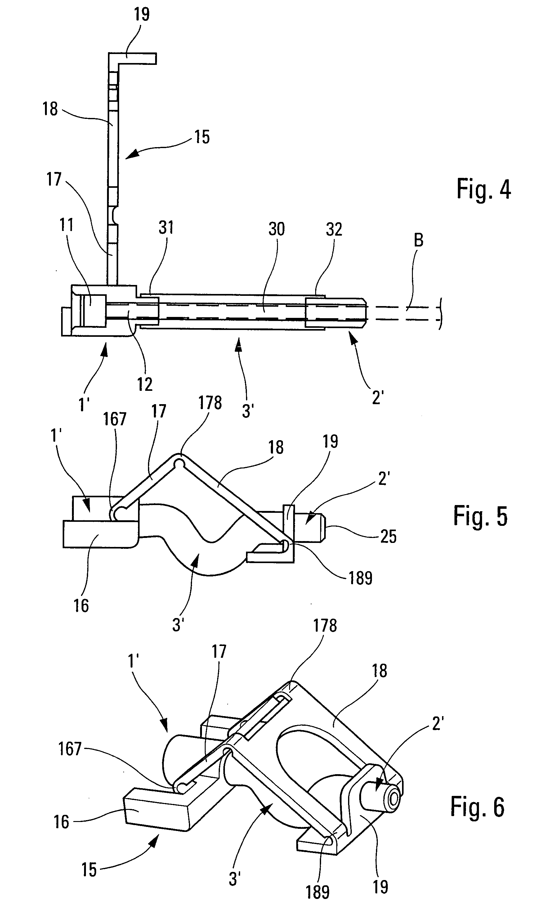
[0028]Reference is made below to FIGS. 4 to 6 in order to explain a dispenser head of the invention.

[0029]This dispenser head likewise comprises an endpiece 1′, a nozzle 2′, and a flexible hose 3′ that is injection-molded on the endpiece 1′ and / or on the nozzle 2′. The endpiece 1′ includes a connection sleeve 11 for mounting on the outlet from a dispenser member. The endpiece includes an internal channel 12 that puts the sleeve 11 into communication with the internal duct 30 of the flexible hose 3. The flexible hose includes a first end 31 that is injection-molded on the endpiece 1′, and a second end 32 that is injection-molded on the nozzle 2′. In this embodiment, the nozzle 2′ defines a simple dispenser orifice providing an outlet without the fluid being sprayed. However, it is also possible to imagine that the nozzle 2′ performs spraying. As in the first embodiment, the internal duct 30 and the internal channel 12 can be made by means of a rectilinear pin B that can be inserted s...


PUM

PropertyMeasurementUnit
flexibleaaaaaaaaaa
shapeaaaaaaaaaa
displacementaaaaaaaaaa

Abstract

A fluid dispenser head for mounting on an outlet from a fluid dispenser member such as a pump or a valve, the head comprising:an endpiece (1) that is adapted to be mounted on the outlet from the dispenser member;a fluid dispenser nozzle (2) through which the fluid leaves the head; anda flexible hose (3) connecting the endpiece (1) to the nozzle (2);the hose being injection-molded on the endpiece (1) and / or on the nozzle (2).

Description

CROSS REFERENCE TO RELATED APPLICATION[0001]This application claims the benefit under 35 U.S.C. §119(e) of pending U.S. provisional patent application Ser. No. 60 / 834,802, filed Aug. 2, 2006, and priority under 35 U.S.C. §119(a)-(d) of French patent application No. FR-06.51592, filed May 4, 2006.TECHNICAL FIELD[0002]The present invention relates to a fluid dispenser head for mounting on an outlet from a fluid dispenser member such as a pump or a valve. The present invention also relates to a method of manufacturing such a head. The present invention also relates to a fluid dispenser comprising a reservoir, a dispenser member such as a pump or a valve, and a dispenser head of the invention. Preferred, but non-exclusive, fields of application of the present invention are perfumery, cosmetics, and pharmacy.BACKGROUND OF THE INVENTION[0003]The head of the present invention is a particular type comprising an endpiece for mounting on, or associating with, the outlet from a pump or a valve...

Claims


Application Information

Patent Timeline
Patent Type & Authority Applications(United States)
IPC IPC(8): B67D3/00F16K7/04
CPCB05B11/3015B05B11/3042B65D83/303B29L2023/005B65D83/205B29C45/1676B05B11/1015B05B11/1042
Inventor PARMENTIER, ALEXANDRAMICHAUX, SEBASTIEN
Owner VALOIS SA
Why Eureka
Try Eureka