Ice Drill

a drill and ice technology, applied in the field of ice drills, can solve the problems of difficult boring, uncomfortable hits and pulls, and difficult boring, and achieve the effects of improving drilling smoothness, easy and reliable extraction, and easy production of attachments

Inactive Publication Date: 2007-11-08
MORA OF SWEDEN
View PDF5 Cites 13 Cited by
  • Summary
  • Abstract
  • Description
  • Claims
  • Application Information

AI Technical Summary

Benefits of technology

[0010] By arranging such a support surface in connection with the cutting blade, preferably in the intended direction of rotation substantially directly in front of the cutting blade, the cutting depth will be well defined when drilling, so that an even and fine operation is obtained when drilling through the ice, without uncomfortable hits and pulls in the arm for very different ice types. This means also that the very drilling gets less tiring.
[0019] According to another preferred embodiment of the invention said spiral is together with a sleeve being central with respect thereto moulded into one piece of a plastic material, and the sleeve receives and is secured to a rigid drill rod extending therethrough, preferably of metal. The completely unique about making a spiral on an ice drill of plastic material means a considerable saving of weight with respect to conventional ice drills having a spiral of steel. This is an important advantage, since the ice drills are often carried along by hand or are attached to a rucksack or the like. Furthermore, a spiral of this type may be manufactured in larger series to a lower cost than a steel spiral which has to be welded to the drill rod. Another advantage is that the manufacturing accuracy of the spiral may be increased.

Problems solved by technology

The ice drills known until now have a tendency to occasionally treat the ice irregularly and deliver uncomfortable hits and pulls to the arm of the person drilling by means of the ice drill or holding it.
This problem varies depending upon the nature of the ice, and it may for some ice be experienced as very uncomfortable and irritating to have the irregular operation of the cutting blades and the drill when drilling.
This makes the boring more difficult and makes the person carrying out the drilling tired.
This problem gets greater the more holes are to be drilled on one day and the thicker the ice.

Method used


Image

  • Ice Drill
  • Ice Drill
  • Ice Drill

Examples


Embodiment Construction

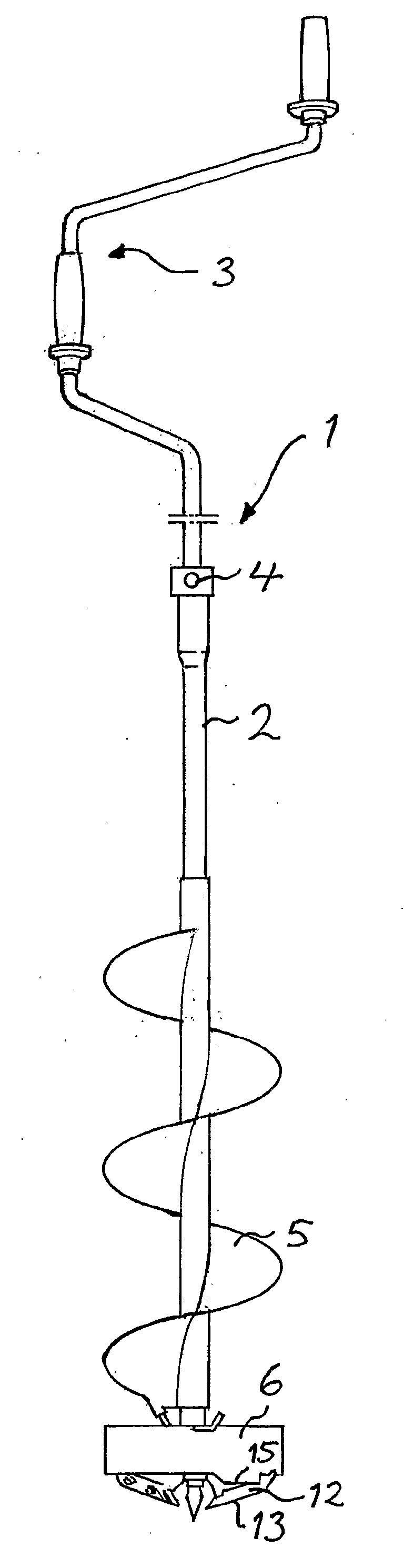
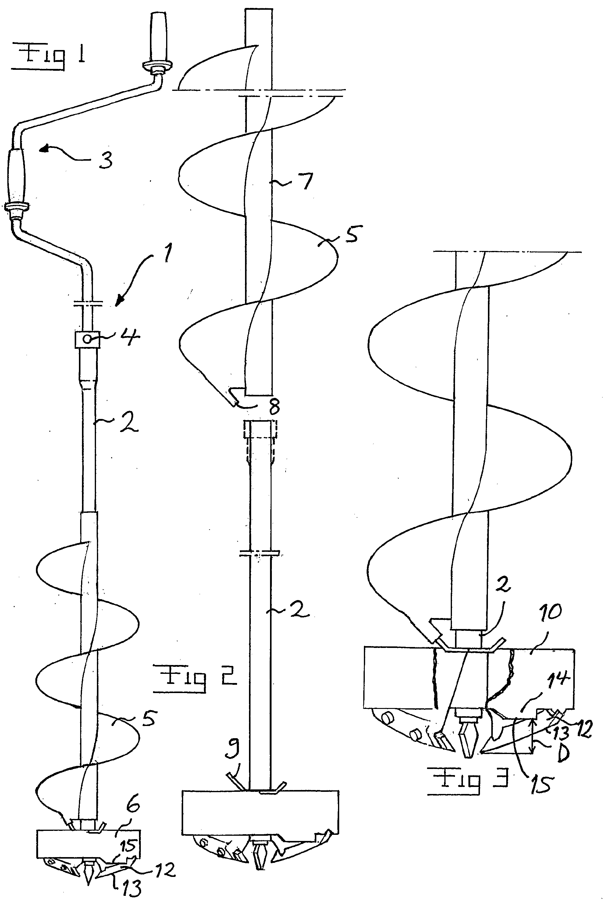
[0031] An ice drill 1 according to an embodiment of the present invention is illustrated in FIG. 1. This has a central rigid drill rod 2, which for example is made of stainless steel or surface treated steel. A crank 3 is removably secure to the drill rod at 4 so as to be able to drive the drill rod 2 to rotate around the axis thereof.

[0032] A spiral 5 extends around the drill rod from the region of a bore crown 6 and upwards for lifting crushed ice formed by the drilling. The spiral 5 is in the present case moulded of plastic material in one single piece with a sleeve 7 central with respect thereto. It is illustrated in FIG. 2 how this piece moulded of plastic is moved onto the drill rod upon manufacturing thereof to the position according to FIG. 1, where a recess 8 in the spiral receives a projection 9 extending from the drill rod and the spiral is then shrank onto the drill rod 2. By the manufacture of the spiral 5 in this way of plastic material it gets an advantageous very lo...


PUM


Abstract

A tool for drilling holes through ice has a central drill rod (2) having a spiral (5) for lifting crushed ice formed by the drilling, a carrier (6) attached to one end of the drill rod (2) and being fixed to at least one cutting blade (12) extending substantially radially with respect the drill rod (2) and having a cutting edge (13) for cutting and thereby drilling into the ice upon rotation of the drill rod (2). A member is fixed with respect to the carrier (6) for support on the ice through a surface (15) at a distance in the direction of the axis of the drill rod (2) in the drilling direction behind the cutting edge of the cutting blade (12) for defining the cutting depth when drilling by the tool.

Description

FIELD OF THE INVENTION AND PRIOR ART [0001] The invention relates to a tool for drilling a hole through thick outdoor ice, on lakes and the like, which comprises a central drill rod having a spiral therearound for lifting crushed ice formed by the drilling, a carrier attached to one end of the drill rod and having fixed thereto at least one cutting blade extending substantially radially with respect to the drill rod and having a cutting edge for cutting and thereby drilling into the ice upon rotation of the drill rod. [0002] Such a tool is normally called ice drill, for what reason this expression will be used hereinafter. [0003] Outdoor ice means ice on lakes, rivers, oceans and the like, where a flowing water is present under the ice. [0004] Such an ice drill is normally used for making holes through ice for fishing, such as jigging, but other intensions of the hole production is also possible. Such ice drills may be designed to make holes with varying diameters, in which a typica...

Claims


Application Information

Patent Timeline
Patent Type & Authority Applications(United States)
IPC IPC(8): F25C5/04A01KA01K97/01B23B51/00E21B7/00F25C5/16
CPCA01K97/01B23B51/00B23B2226/48F25C5/16E21B7/008F25C5/043B23B2226/61F25C5/00F25C5/02
Inventor NORLING, TORE
Owner MORA OF SWEDEN
Why Eureka
Try Eureka