
Apparatus and method for cleaning, neutralizing carbon monoxide and recirculating exhaust air in a confined environment

a technology of confined environment and recirculating air, which is applied in the direction of combustible gas purification/modification, chemical/physical processes, domestic heating, etc., can solve the problems of large amount of air consumed from within the confined environment to exhaust contaminants, carbon monoxide, toxic and may be lethal in concentrated doses, etc., to reduce the capacity of heating, cooling and air conditioning equipment, and avoid losing the energy content of conditioned air. , the effect of reducing

Inactive Publication Date: 2007-11-01
HOPKINS DANNY L
View PDF3 Cites 5 Cited by
  • Summary
  • Abstract
  • Description
  • Claims
  • Application Information

AI Technical Summary

Benefits of technology

[0009] One primary improvement available from the present invention is an improved capability to remove offensive and harmful particulate and gaseous contaminants from an exhaust flow, and to convert toxic carbon monoxide gaseous contaminants of the exhaust flow into neutralized or benign non-toxic carbon dioxide components, thereby allowing the cleaned and neutralized exhaust flow to be recirculated back into a confined environment of a commercial or industrial establishment. Another improvement relates to recirculating a significant portion of the cleaned and benign exhaust flow to avoid losing the energy content of the conditioned air which is part of the exhaust flow. Another improvement relates to reducing the capacity of the heating, cooling and air conditioning equipment and reducing the cost of operating that equipment to condition makeup air to compensate for the air consumed by the exhaust flow. The operating costs of a food preparation establishment, or any other type of industrial or commercial establishment are substantially reduced.
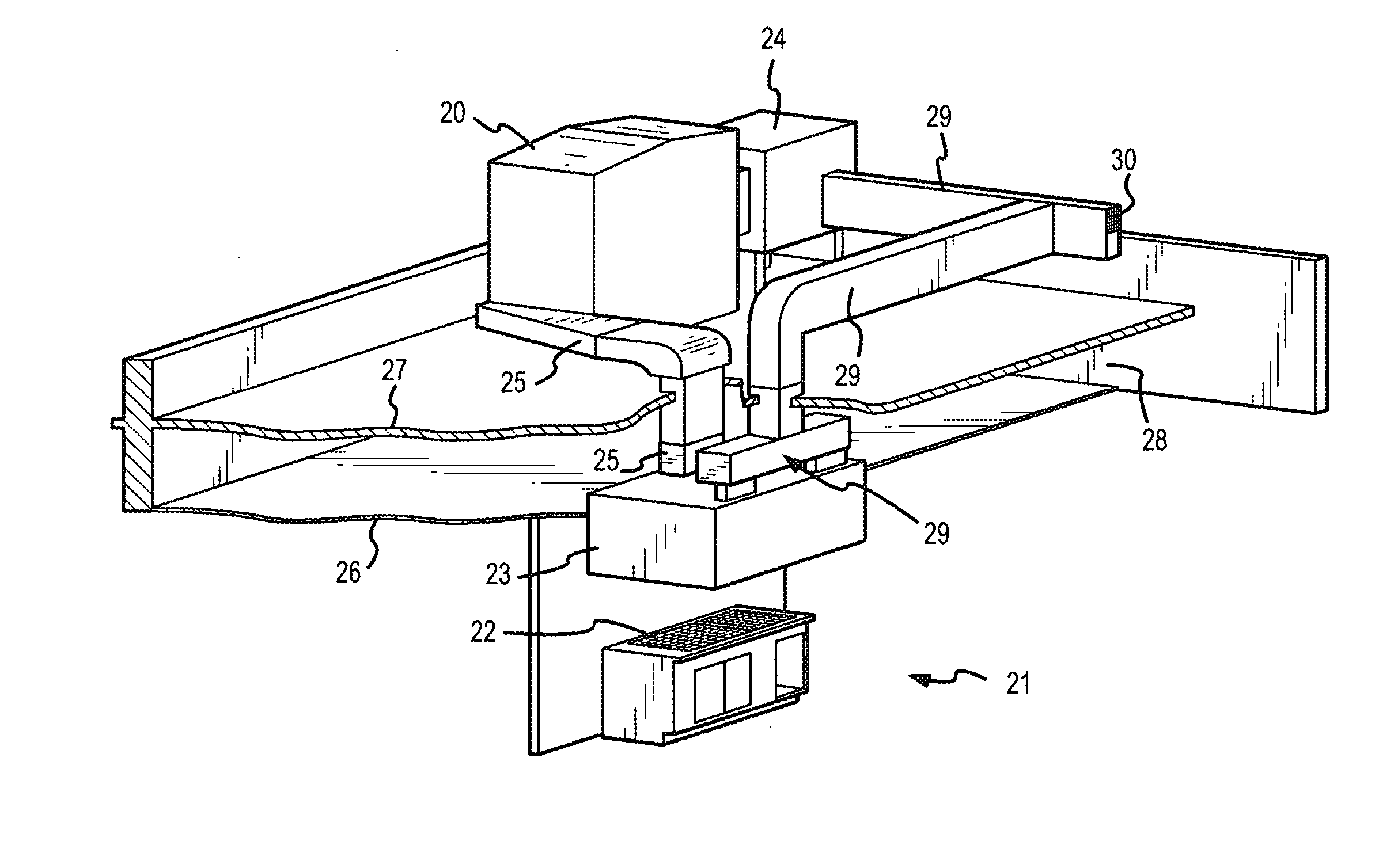
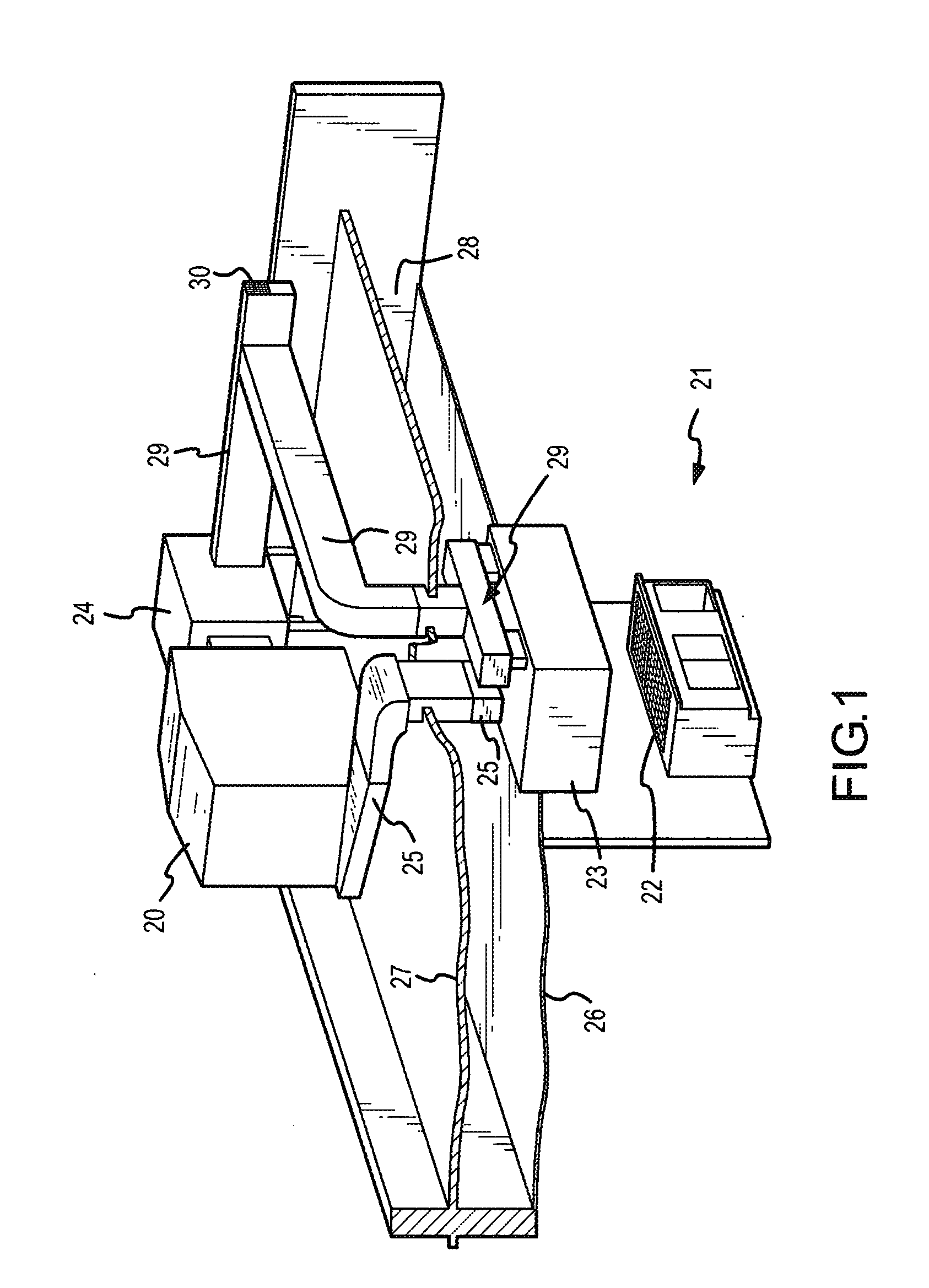
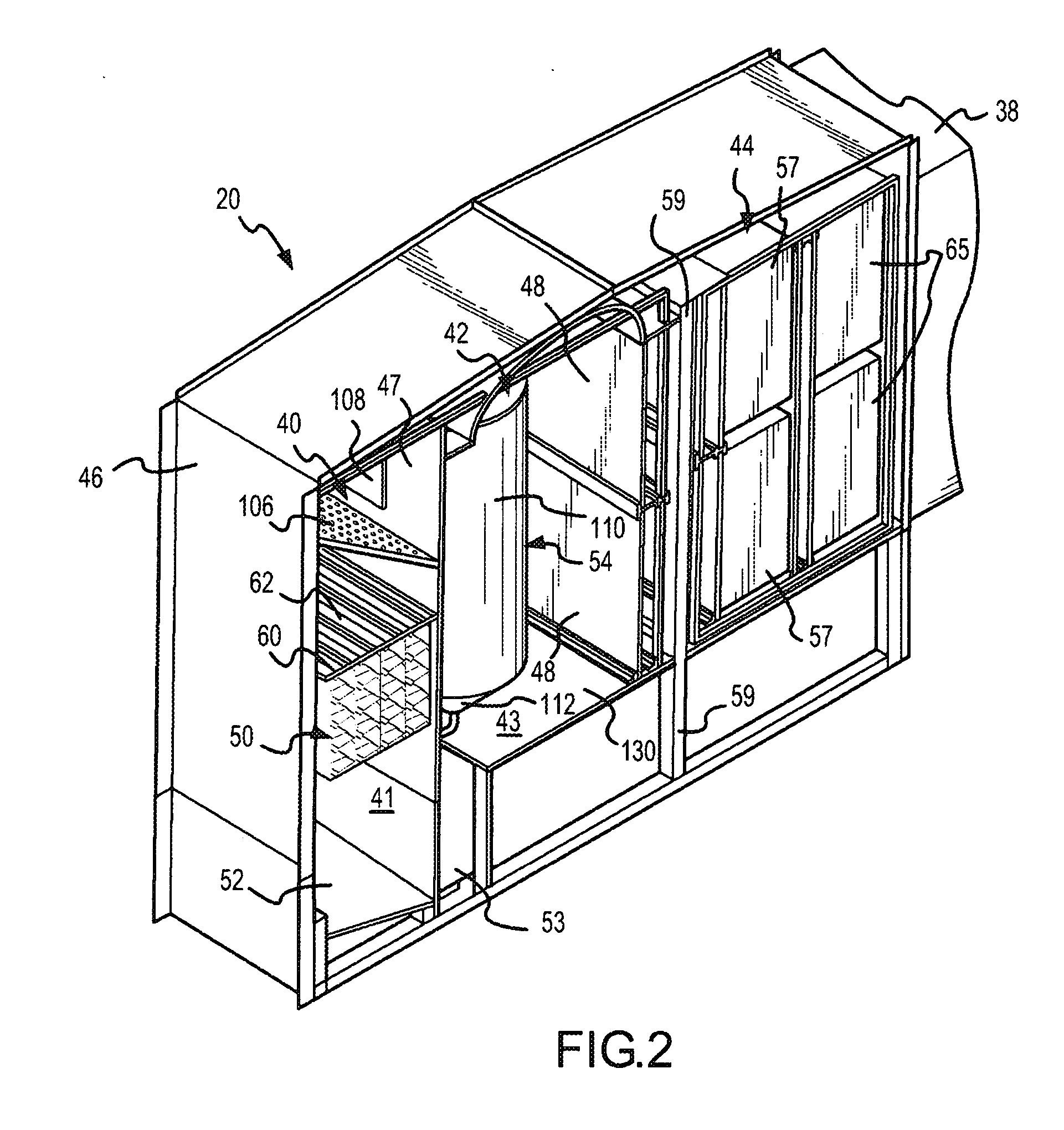
[0010] These and other improvements are achieved in a recirculation system for retaining substantial thermal energy content of air drawn from within a confined environment in which offensive and toxic particulate and gaseous contaminants are generated. The recirculation system includes a collector device located within the confined environment to receive and establish a flow of the exhaust contaminants and air from within the confined environment, and a cleaner device connected to receive the flow of the exhaust contaminants and air from the exhaust collector device. The cleaner device comprises a scrubber module, a liquid removal module and a filtering and conversion module through which the exhaust flow passes. The scrubber module may include flow passageways through which the flow of exhaust contaminants and air passes and into which cleaning liquid is distributed for mixture with and entrainment of the particulate contaminants of the flow. The liquid removal module removes the cleaning liquid from the flow from the scrubber module. The filtering and conversion module includes an odor-removing filter for removing odor from the exhaust flow from the liquid removal module. The filtering and conversion module also includes a room-temperature catalyst which facilitates conversion of toxic carbon monoxide gaseous contaminants in the exhaust flow from the liquid removal module into benign carbon monoxide constituents. A delivery device is located within the confined environment to receive the cleaned and neutralized flow from the cleaner device and to discharge the flow into the confined environment.
[0012] The above noted and other improvements are also achieved by a method of recirculating air to retain substantial thermal energy content of the air drawn from within a confined environment of an establishment which generates offensive and harmful particulate and gaseous constituents as exhaust contaminants. The method includes establishing a flow of the exhaust contaminants and air from within the confined environment, liquid scrubbing particulate contaminants from the flow, moving the flow in a curved path to force liquid mist to coalesce into liquid by centrifugal force caused by moving the flow in the curved path, removing the coalesced liquid from the flow, removing odor from the flow after the coalesced liquid has been removed, catalyzing toxic carbon monoxide remaining in the flow into benign carbon dioxide after the coalesced liquid has been removed, and discharging the cleaned and neutralized flow into the confined environment.

Problems solved by technology

Moreover, the hydrocarbon fuels which are burned while cooking the food generate carbon monoxide, which is toxic and may be lethal in concentrated doses.
Some types of these industrial and business operations, such as restaurants or food preparation establishments, generate a relatively large amount of such contaminants, and the amount of air consumed from within the confined environment to exhaust the contaminants is substantial.
Otherwise, the desired thermal environment within the establishment could not be maintained.
The energy required to heat, cool or otherwise condition makeup air may be a significant operating cost of the establishment.
Considerable expense is involved in obtaining the increased capacity of the heating and cooling equipment for conditioning the makeup air, and in operating that equipment.
One of the significant drawbacks to recirculating the exhaust air from confined environments such as food preparation establishments, has been an inability to clean the contaminants from the exhaust air in a cost-efficient manner.

Method used


Image

  • Apparatus and method for cleaning, neutralizing carbon monoxide and recirculating exhaust air in a confined environment
  • Apparatus and method for cleaning, neutralizing carbon monoxide and recirculating exhaust air in a confined environment
  • Apparatus and method for cleaning, neutralizing carbon monoxide and recirculating exhaust air in a confined environment

Examples


Embodiment Construction

[0028] A cleaner 20 embodying part of the present invention is shown in FIG. 1. The cleaner 20 is shown in a typical or exemplary use in a restaurant cooking-exhaust cleaning and recirculating application. However, the use of the invention is not limited to food preparation establishments, but may be used in any confined environment in which a variety of different types of contaminants are created and from which those contaminants must be exhausted in a flow of air. Examples of other business and industrial establishments where the present invention is particularly useful are automobile repair shops, clothes dry cleaning operations, waste and water treatment plants. The contaminants may be any airborne particulate matter of solid or liquid substances or may be molecules of hazardous gaseous substances. For example, in the restaurant cooking-exhaust cleaning application, the contaminants may include grease and fat particles, smoke, volatile organic compounds, carbon monoxide and / or o...


PUM

PropertyMeasurementUnit
angleaaaaaaaaaa
angleaaaaaaaaaa
thickaaaaaaaaaa

Abstract

Exhaust air containing particulate and carbon monoxide gas contaminants is withdrawn from a confined environment, such as a food cooking area, by a circulation system which liquid scrubs particulate contaminants from the exhaust flow, removes liquid mist from the flow, and then catalyzes or neutralizes the carbon monoxide gas contaminants into benign carbon dioxide before discharging the flow back into the confined environment. Removing contaminants in this manner allows a substantial amount of the thermal energy content of the exhaust air to be saved and reused within the confined environment, rather than discharging the thermal energy into the ambient environment.

Description

CROSS-REFERENCE TO RELATED INVENTIONS [0001] This is a continuation of U.S. patent application Ser. No. 10 / 661,214, filed Sep. 12, 2003, now U.S. Pat. No. ______, issued ; which is a division of U.S. application Ser. No. 09 / 873,635, filed Jun. 4, 2001, now U.S. Pat. No. 6,797,247, issued Sep. 28, 2004; which is a continuation-in-part of U.S. patent application Ser. No. 09 / 399,125, filed Sep. 20, 1999, now U.S. Pat. No. 6,241,809, issued Jun. 5, 2001. The disclosures of these inventions are incorporated herein by this reference.INTRODUCTION [0002] This invention relates to a new and improved method and apparatus which eliminates offensive and toxic particulate and gaseous contaminants, such as smoke, grease, volatile organic compounds, carbon monoxide and other toxic gases, from an exhaust flow, and recirculating the cleaned and benign exhaust flow back into a confined environment from which the exhaust originated. In addition to avoiding the discharge of undesirable and potentially ...

Claims


Application Information

Patent Timeline
Patent Type & Authority Applications(United States)
IPC IPC(8): B01D50/00B01D45/06B01D45/10B01D53/18B01D53/74F24C15/20H01L21/02H01L21/768
CPCB01D45/06B01D45/10B01D47/06B01D53/18B01D53/74B01D53/864Y10S55/36B01D2257/502F24C15/20F24C15/2035H01L21/768H01L28/40H01L28/75B01D2221/02Y02P70/10Y02A50/20
Inventor HOPKINS, DANNY L.
Owner HOPKINS DANNY L
Learn More