
High Data Density Volumetic Holographic Data Storage Method and System

a volumetic, high data density technology, applied in the field of holographic data storage system, can solve the problems of high precision drive, large number of holographic materials with invariable size, and complex structure of holographic components

Inactive Publication Date: 2007-11-01
THOMSON LICENSING SA
View PDF9 Cites 28 Cited by
  • Summary
  • Abstract
  • Description
  • Claims
  • Application Information

AI Technical Summary

Benefits of technology

[0014] The central element of the optical system is a writing / reading Fourier objective. As the object and reference beams travel very different distances from the writing objective to the data carrier and from the data carrier to the reading objective, respectively, during writing and reading of the layers situated below each other, the writing / reading Fourier objective is complemented with asymmetric compensating plates whose size and / or thickness depends on the depth of the addressed layer and / or of various optical properties, to compensate the different lengths of the optical paths. The compensating plates are placed in front of the writing / reading Fourier objective and / or between the data carrier and the objective or even within the objective itself. The use of compensating plates of properties (shape, thickness etc.) depending on the depth of the layers enables the layers to be addressed independently of each other.

Problems solved by technology

This, however, raises a number of problems in the field of illumination, mapping and possibility of detecting.
In addition to noise that may occur, other problems need also be taken into account.
The most significant problem is that, in case of a bit-oriented multi-layer disc, 3-dimensional servo systems have to be developed.
The main problems of utilizing multiplexing are: it requires a large M# number of holographic materials with invariable size, high precision drives and expensive optical elements.
The presented solution, however, fails to deal with the handling of errors caused by the maladjustment of data layers and the difficulties caused by the size increase during multiplying the relatively robust layers as well as the possibility of manufacturing the relatively complicated layer structure.
This solution also sets severe requirements to the servo system.

Method used


Image

  • High Data Density Volumetic Holographic Data Storage Method and System
  • High Data Density Volumetic Holographic Data Storage Method and System
  • High Data Density Volumetic Holographic Data Storage Method and System

Examples


Embodiment Construction

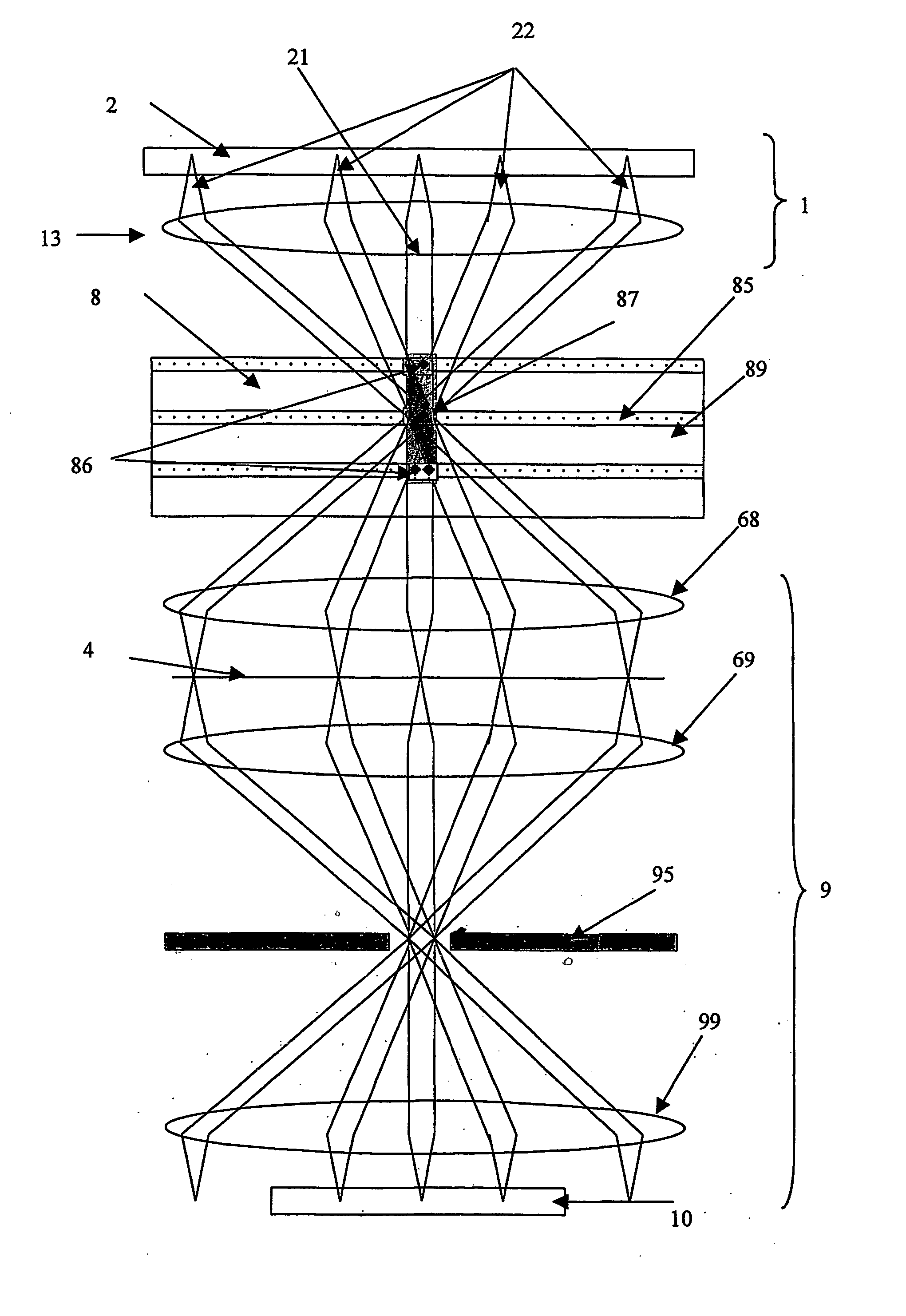
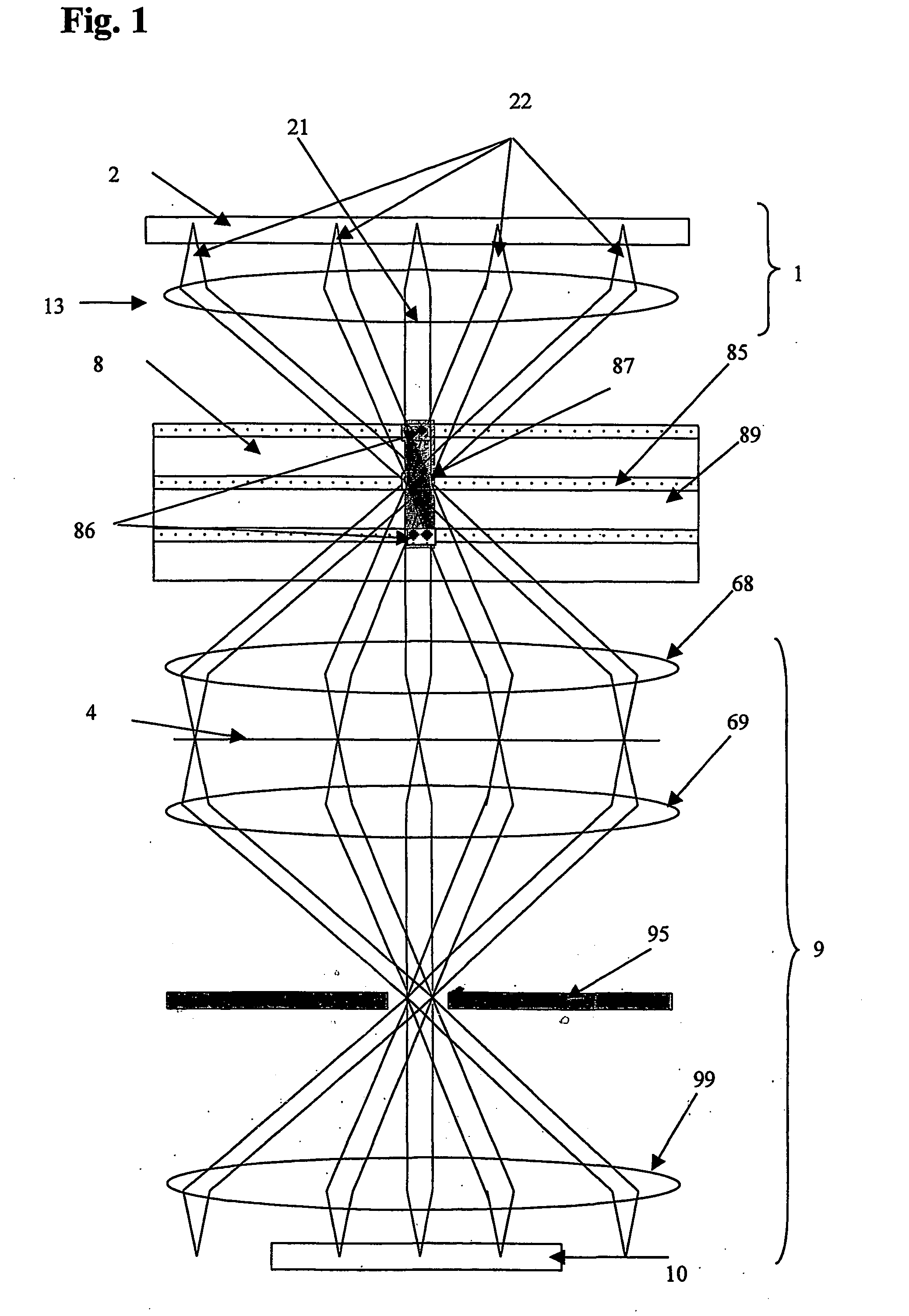
[0036] The optical system shown in FIG. 1 is a complex 8f system, which consists of four different objectives. The elements of each objective may be expediently identical. The first Fourier objective 13 generates the Fourier transform of the object (SLM, spatial light modulator) and the second member retransforms the object. The image of the object is created in the back focal plane of the second Fourier objective 68. The SLM 2 located in the first focal plane of the first objective serves for writing the data. The first focal plane of the third Fourier objective 69 coincides with the back focal plane of the second Fourier objective 68. The image of the SLM is in this plane 4. This image is transformed to the back focal plane by the third Fourier objective 69. The fourth Fourier objective 99 retransforms the image of the SLM. Hence, the image of the SLM appears again in the back focal plane of the fourth Fourier objective. This is where the detector array 10 is located. The data car...


PUM


Abstract

The object of the invention is a high data density holographic data storage method. The holograms are written into the volumetric data storage layer or layers, and during the writing process the accurate places of holograms in the data carrier structure are determined by the intersection domain of the object and reference beam or beams, and during the reading process the selection of holograms simultaneously illuminated by the reference beam or beams, the read-out of the addressed hologram, and the suppressing of un-addressed holograms are carried out by a spatial filter located confocally with the addressed hologram and / or by satisfying the Bragg condition. The optical arrangement for recording and reading out holograms has three dedicated planes in confocal arrangements, where the addressed hologram is in the middle dedicated plane in the storage material, and in the two outer dedicated planes there are spatial filters. The optical arrangement is a 12f optical System consisting of three pairs of objectives.

Description

FIELD OF THE INVENTION [0001] The invention describes a new kind of holographic data storage system, which is capable of obtaining a capacity of 200 to 800 Gbytes using a disc of 1 to 3 mm thickness and 120 mm diameter. The system presented here achieves the high capacity by means of 3-dimensional multi-layer holographic data storage. High-speed reading is ensured by parallel reading and by the disc format. Addressing of various layers in the system is implemented by means of a confocal optical arrangement, which, at the same time, also filters out holograms that are read but un-addressed. The addressed hologram and a spatial filter are arranged in a confocal optical system. BACKGROUND OF THE INVENTION [0002] When comparing the data storage possibilities available in our days, it can be stated that, in the field of data storage using e.g. CD and DVD, one of the feasible ways to increase the capacity is the reduction of wavelength, which involves the trend towards the UV spectrum. Th...

Claims


Application Information

Patent Timeline
IPC IPC(8): G11B7/0065G03H1/26G11B7/00
CPCG11B7/0065G03H1/26
Inventor SZARVAS, GABORKOPPA, PALERDEI, GABORDOMJAN, LASZLOKALLO, PETER
Owner THOMSON LICENSING SA
Learn More