
System and method for melting solid ink sticks in a phase change ink printer

a phase change ink printer and solid ink technology, applied in the field of machines, can solve the problems of limiting or reducing imaging speed, increasing sensitivity to resistance and pressure in the flow path affecting the flow rate of the print head, so as to increase the flow rate of melted ink exit, reduce the melting time, and increase the pressure within the enclosure

Inactive Publication Date: 2007-11-01
XEROX CORP
View PDF21 Cites 8 Cited by
  • Summary
  • Abstract
  • Description
  • Claims
  • Application Information

AI Technical Summary

Benefits of technology

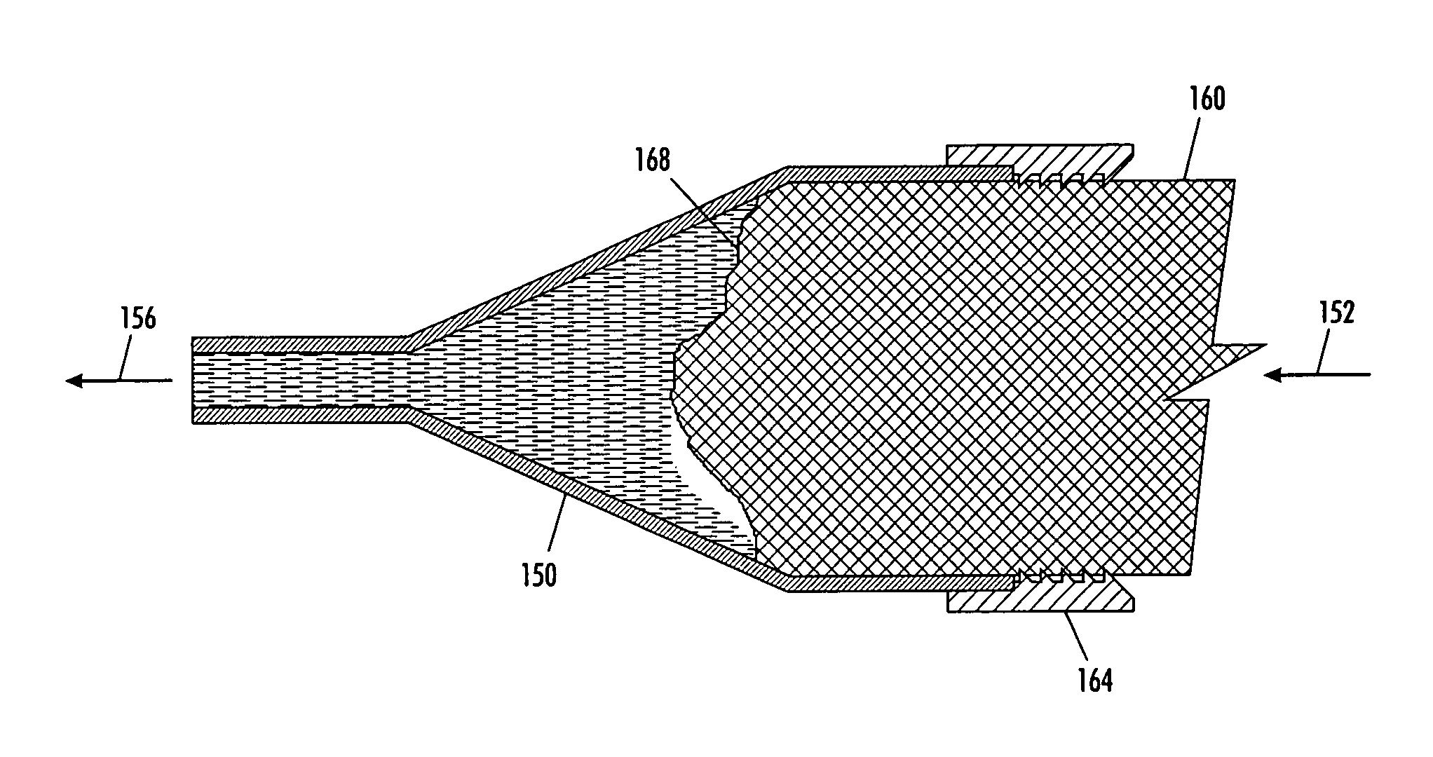
[0010] An improved solid ink stick heating chamber provides decreased melting time and increased melted ink exit flow rates. The heating chamber comprises an ink stick melt chamber having an enclosure with at least one heated wall, an inlet for receiving an ink stick, and an outlet for melted ink flow from the enclosure, and a seal mounted proximate the inlet to engage an ink stick passing through the seal so that the seal and the ink stick form a barrier and retain melted ink within the enclosure. The seal stops the melted ink within the chamber from exiting the enclosure at the inlet. As additional ink sticks are driven through the seal, the pressure within the enclosure increases. The increased pressure enables the chamber to deliver liquid ink at adequate flow rates to the print head.
[0011] An improved method for supplying ink to a print head in a phase change printer includes moving ink sticks to an inlet of an ink stick melt chamber having an enclosure with at least one opening, urging ink sticks through a seal mounted proximate the inlet, heating the enclosure to melt ink sticks within the enclosure of the ink stick melt chamber, and blocking leakage of melted ink from the inlet of the ink stick melt chamber with the seal so the melted ink exits the ink stick melt chamber with sufficient pressure to pass through a filter before entering a print head of the printer.

Problems solved by technology

One problem arising from higher throughput rates is increased sensitivity to resistance and pressures in the print head flow path.
Restricted ink flow can limit or decrease imaging speed.
In systems having filtration systems for filtering the liquid ink between the reservoir and a print head element, the flow may also change over time and become insufficient to draw liquid ink to the print head in sufficient amounts to provide the desired print quality.
Increasing the filter area, however, also increases the cost of the printer as filtration material is often expensive.
Moreover, the space for a larger filter may not be available as space in the vicinity of a print head of in a phase change printer is not always readily available.
The approach of introducing pressure, however, increases the complexity of the printing system, adds a pressure source and related components to the printer, and introduces another maintenance issue for the operational life of the printer.
One limitation of the tapered melt chambers is the additional opportunity for flow away from the chamber at points other than the intended exit point near the smaller portion of the tapered geometry.
As noted previously, space constraints may be rather restrictive in some phase change ink printers, which makes it difficult or impossible to configure the ink delivery system to rely on gravity flow control.
Also, space above the print head may not be available for a melt chamber having an adequate length to width ratio to achieve the desired melt surface area.

Method used


Image

  • System and method for melting solid ink sticks in a phase change ink printer
  • System and method for melting solid ink sticks in a phase change ink printer
  • System and method for melting solid ink sticks in a phase change ink printer

Examples


Embodiment Construction

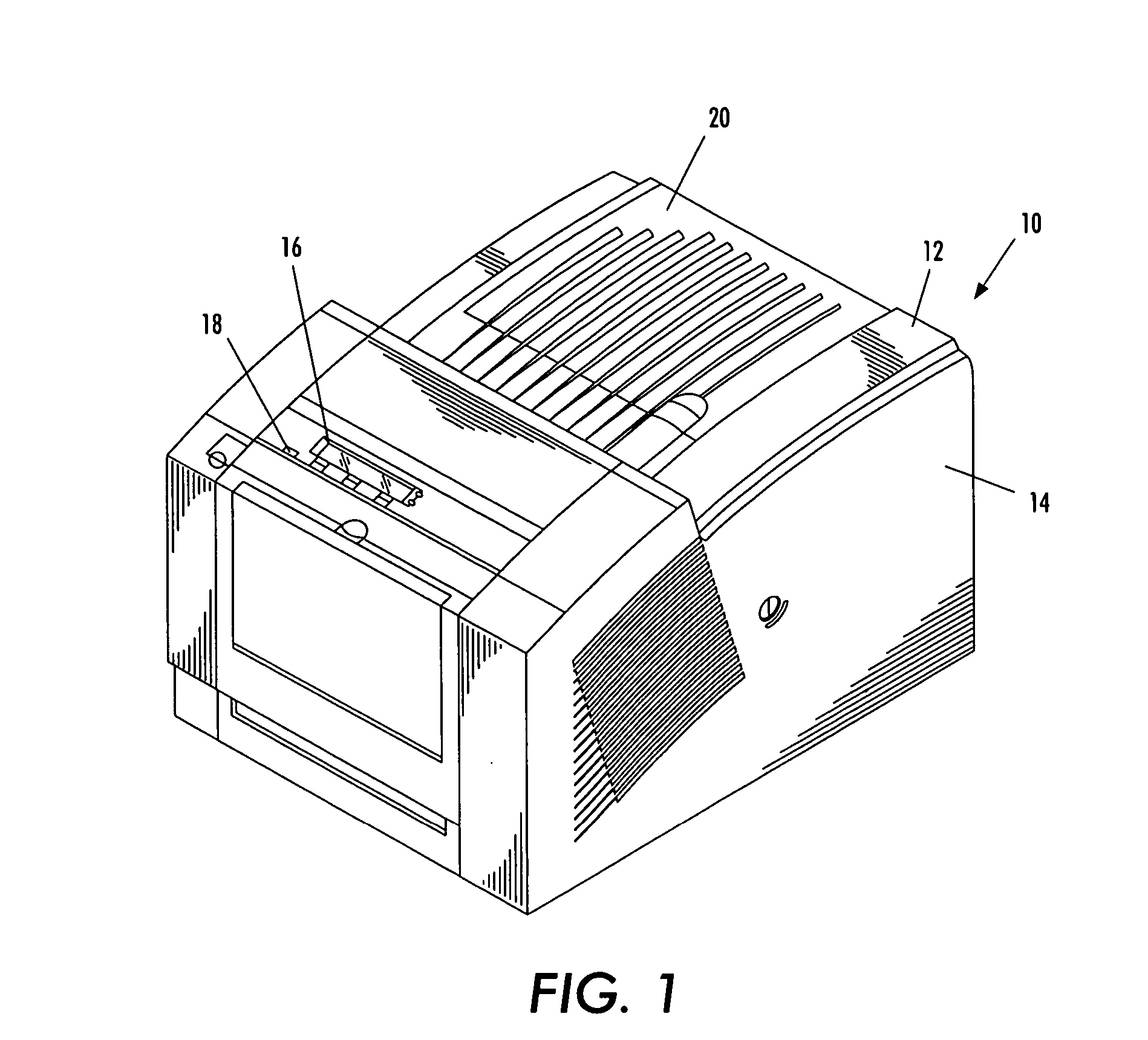
[0021] Referring to FIG. 1, there is shown a perspective view of an ink printer 10 that incorporates a solid ink stick melting chamber that melts solid ink sticks and delivers the melted ink to a print head with sufficient pressure to overcome the fluid resistance of a filter. The reader should understand that the embodiment discussed herein may be implemented in many alternate forms and variations. In addition, any suitable size, shape or type of elements or materials may be used.

[0022]FIG. 1 shows an ink printer 10 that includes an outer housing having a top surface 12 and side surfaces 14. A user interface display, such as a front panel display screen 16, displays information concerning the status of the printer, and user instructions. Buttons 18 or other control elements for controlling operation of the printer are adjacent the user interface window, or may be at other locations on the printer. An ink jet printing mechanism (FIG. 3) is contained inside the housing. An ink feed ...


PUM


Abstract

A solid ink stick melting apparatus is incorporated in a phase change printer to provide melted ink under pressure to a print head. The solid ink stick melting apparatus includes an ink stick melt chamber having an enclosure with at least one heated wall, an inlet for receiving an ink stick, and an outlet for melted ink flow from the enclosure, and a seal mounted proximate the inlet to engage an ink stick passing through the seal so that the seal and the ink stick form a barrier and retain melted ink within the enclosure.

Description

TECHNICAL FIELD [0001] This disclosure relates generally to machines that use phase change materials, and more particularly, to machines that melt solid phase change ink for imaging. BACKGROUND [0002] Solid ink or phase change ink printers conventionally use ink in a solid form, either as pellets or as ink sticks of colored cyan, yellow, magenta and black ink, that are inserted into feed channels through openings to the channels. Each of the openings may be constructed to accept sticks of only one particular configuration. Constructing the feed channel openings in this manner helps reduce the risk of an ink stick having a particular characteristic being inserted into the wrong channel. U.S. Pat. No. 5,734,402 for a Solid Ink Feed System, issued Mar. 31, 1998 to Rousseau et al.; and U.S. Pat. No. 5,861,903 for an Ink Feed System, issued Jan. 19, 1999 to Crawford et al. describe exemplary systems for delivering solid ink sticks into a phase change ink printer. [0003] After the ink sti...

Claims


Application Information

Patent Timeline
Patent Type & Authority Applications(United States)
IPC IPC(8): B41J2/175
CPCB41J2/175B41J2/17593B41J2/17509B41J2/17
Inventor PLATT, DAVID PAULJONES, BRENT RODNEY
Owner XEROX CORP
Learn More