
Shift actuator, vehicle, and method of integrating vehicle

a technology of shift actuator and vehicle, which is applied in the direction of crankshaft transmission, friction roller based transmission, cycles, etc., can solve the problems of complicated adjustment of the reference position of the shift mechanism, and achieve the effect of simplifying the adjustment of the preferred configuration, improving assembly ease, and easy adjustmen

Active Publication Date: 2007-11-01
YAMAHA MOTOR CO LTD
View PDF22 Cites 17 Cited by
  • Summary
  • Abstract
  • Description
  • Claims
  • Application Information

AI Technical Summary

Benefits of technology

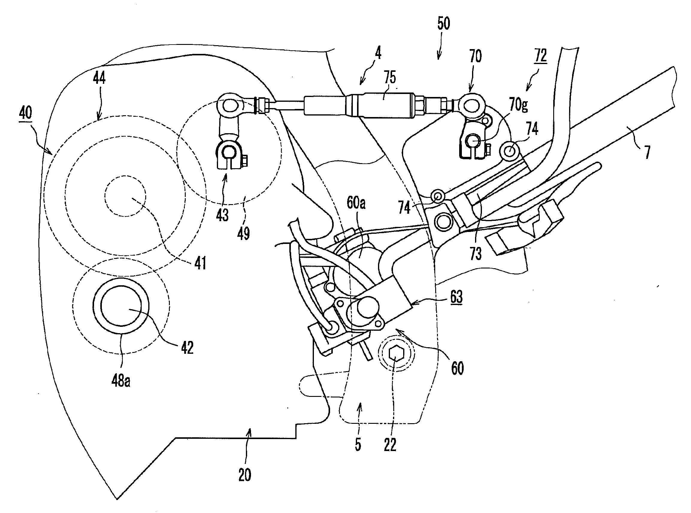
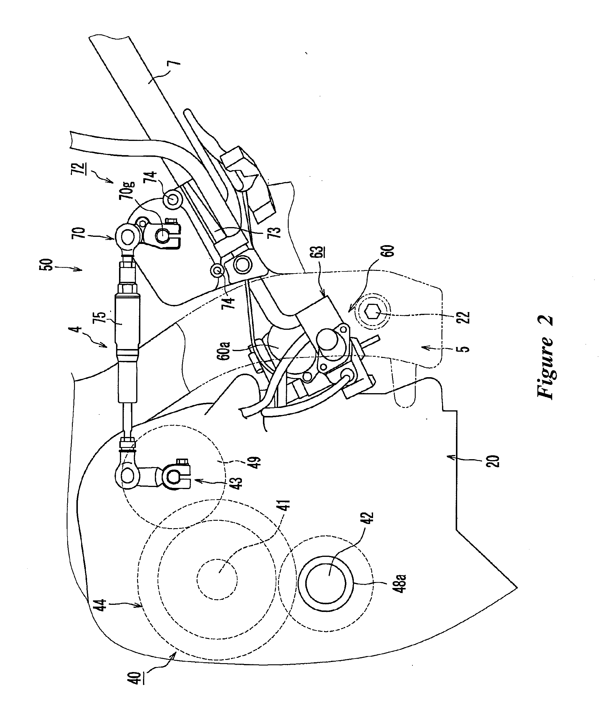
[0011]Upon a review of the early AMT mechanism, two factors have been identified that complicate adjustment of the reference position of the shift mechanism. One factor is that portions to be adjusted are present in two different locations (i.e., the position sensor and the shift power transmitting mechanism). Another factor is that both of the two adjustable portions are directly or indirectly connected to the drive shaft. As a result of intensive investigation of how to simplify calibration of the shift actuator, it has been found that when the drive shaft is temporarily secured against substantial rotation relative to a housing, adjustment of the two portions can be performed easily and independently.
[0016]In one configuration, the position sensor can be attached to the housing with the drive shaft temporarily locked and, therefore, a position of the position sensor can easily be adjusted. Further, separately from the shift power transmitting mechanism, the position of the position sensor can be adjusted by a single member of the shift actuator. Therefore, ease of assembly can be improved. Further, the length of the shift power transmitting mechanism can be adjusted with the drive shaft temporarily locked in position and, therefore, in comparison with the background art of adjusting the length while looking at the output value of the sensor, adjustment of the preferred configuration is simplified. In addition, the length of the shift power transmitting mechanism can be adjusted independently from adjustment of the position of the position sensor and, therefore, both ease of assembly and ease of maintenance are improved.

Problems solved by technology

Upon a review of the early AMT mechanism, two factors have been identified that complicate adjustment of the reference position of the shift mechanism.

Method used


Image

  • Shift actuator, vehicle, and method of integrating vehicle
  • Shift actuator, vehicle, and method of integrating vehicle
  • Shift actuator, vehicle, and method of integrating vehicle

Examples


Embodiment Construction

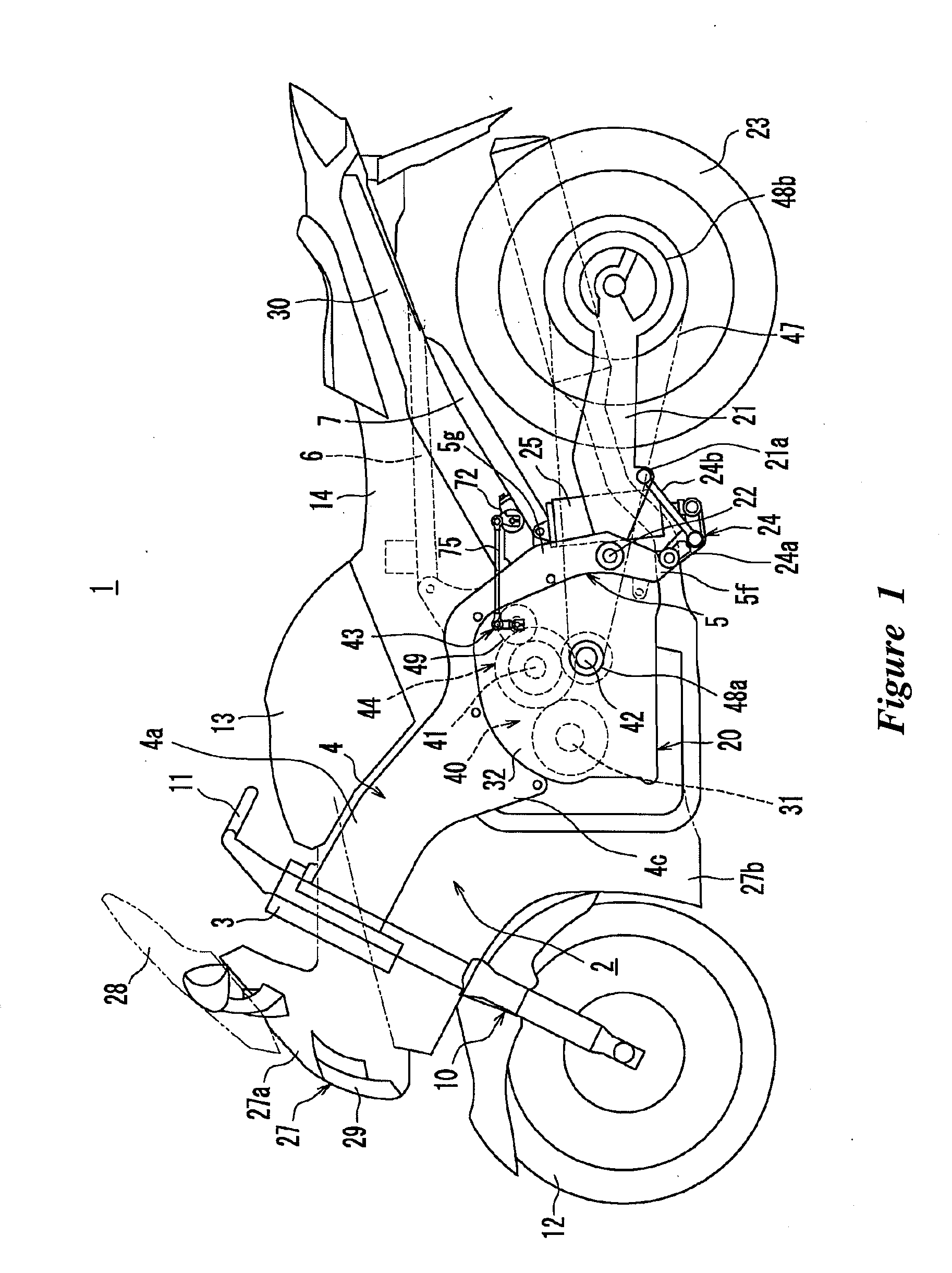
[0028]FIG. 1 is a side view showing a motorcycle 1 that is arranged and configured in accordance with certain features, aspects and advantages of an embodiment of the invention. As shown by FIG. 1, the motorcycle 1 comprises a head pipe 3 and a vehicle body frame 2. The vehicle body frame 2 comprises a main frame 4 that extends rearward from the head pipe 3. The vehicle body frame 2 also comprises a rear arm bracket 5 that extends generally downward from a rear portion of the main frame 4. The main frame 4 comprises a left frame portion 4a and a right frame portion 4a (only the left frame portion 4a is shown in FIG. 1). The frame portions 4a extend rearward from the head pipe 3. The rear portions of the frame portions 4a extend downward and connect to the rear arm bracket 5.

[0029]A front fork 10 is supported by the head pipe 3. An upper end of the front fork 10 is connected to a steering handle 11 while a lower end of the front fork 10 is supported by a front wheel 12. A fuel tank 1...


PUM


Abstract

A shift actuator comprises a drive shaft and a housing that rotatably supports the drive shaft. A shift position detecting apparatus detects a rotational position of the drive shaft. The drive shaft is connected to a shift mechanism by an operating lever and a shift rod. The operating lever and the housing are respectively formed with a through hole and a bottomed hole. The drive shaft can be temporarily secured in rotational position by inserting a lever positioning pin into the through hole and the bottomed hole. When secured, the shift position detecting apparatus can be attached to the housing and a length of the shift rod can be adjusted.

Description

CROSS-REFERENCE TO RELATED APPLICATIONS[0001]This application claims the priority benefit of Japanese Patent Application No. 2006-114707, filed Apr. 18, 2006, which is hereby incorporated by reference in its entirety.BACKGROUND OF THE INVENTION[0002]1. Field of the Invention[0003]The present application generally relates to a shift actuator, a vehicle, and a method of assembling a vehicle.[0004]2. Description of the Related Art[0005]A motorcycle is popular type of vehicle. Motorcycles typically comprise an engine and a transmission. The transmission alters a rotational speed of a crankshaft of the engine while transmitting power from the crankshaft to a drive wheel. The transmission can comprise a shift mechanism, a main shaft, a drive shaft and a plurality of speed change gear combinations. A clutch mechanism can be positioned between the engine and the transmission such that rotation of the transmission can be stopped while the gear combination is changed.[0006]At least one motorc...

Claims


Application Information

Patent Timeline
IPC IPC(8): B62M7/00
CPCB62K11/04F16H2057/0056F16H63/30F16H59/70
Inventor KOSUGI, MAKOTO
Owner YAMAHA MOTOR CO LTD
Learn More