
Electrophotographic photoconductor, image forming apparatus, and process cartridge

Inactive Publication Date: 2007-10-25
RICOH KK
View PDF37 Cites 21 Cited by
  • Summary
  • Abstract
  • Description
  • Claims
  • Application Information

AI Technical Summary

Benefits of technology

[0023]The object of the present invention is to provide a single-layer photoconductor has high sensitivity, and does not generate an abnormal image such as afterimage even after repeated use.

Problems solved by technology

In general, the carriers are easily accumulated because the charge transporting ability of the electron transporting material is not sufficient.

Method used


Image

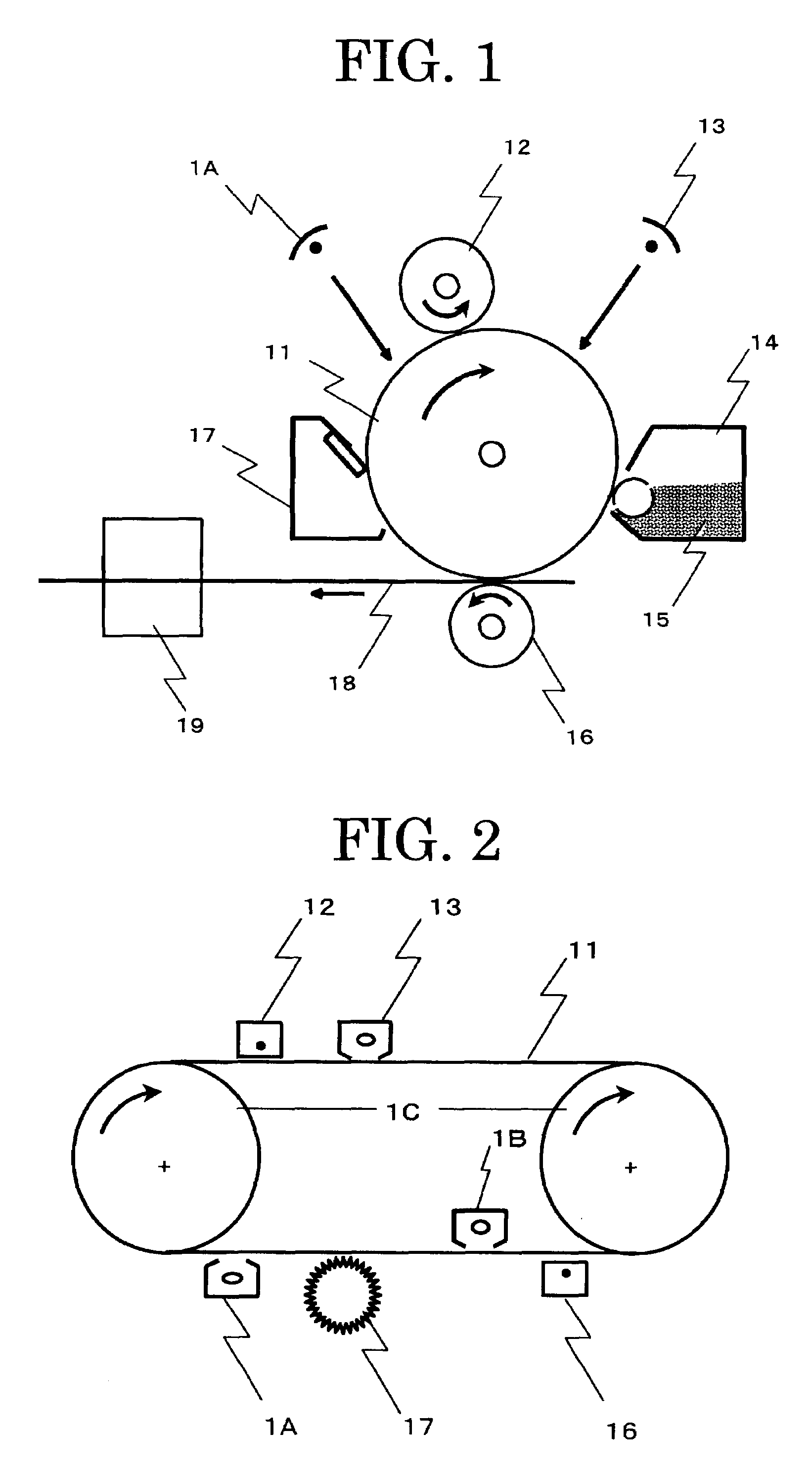
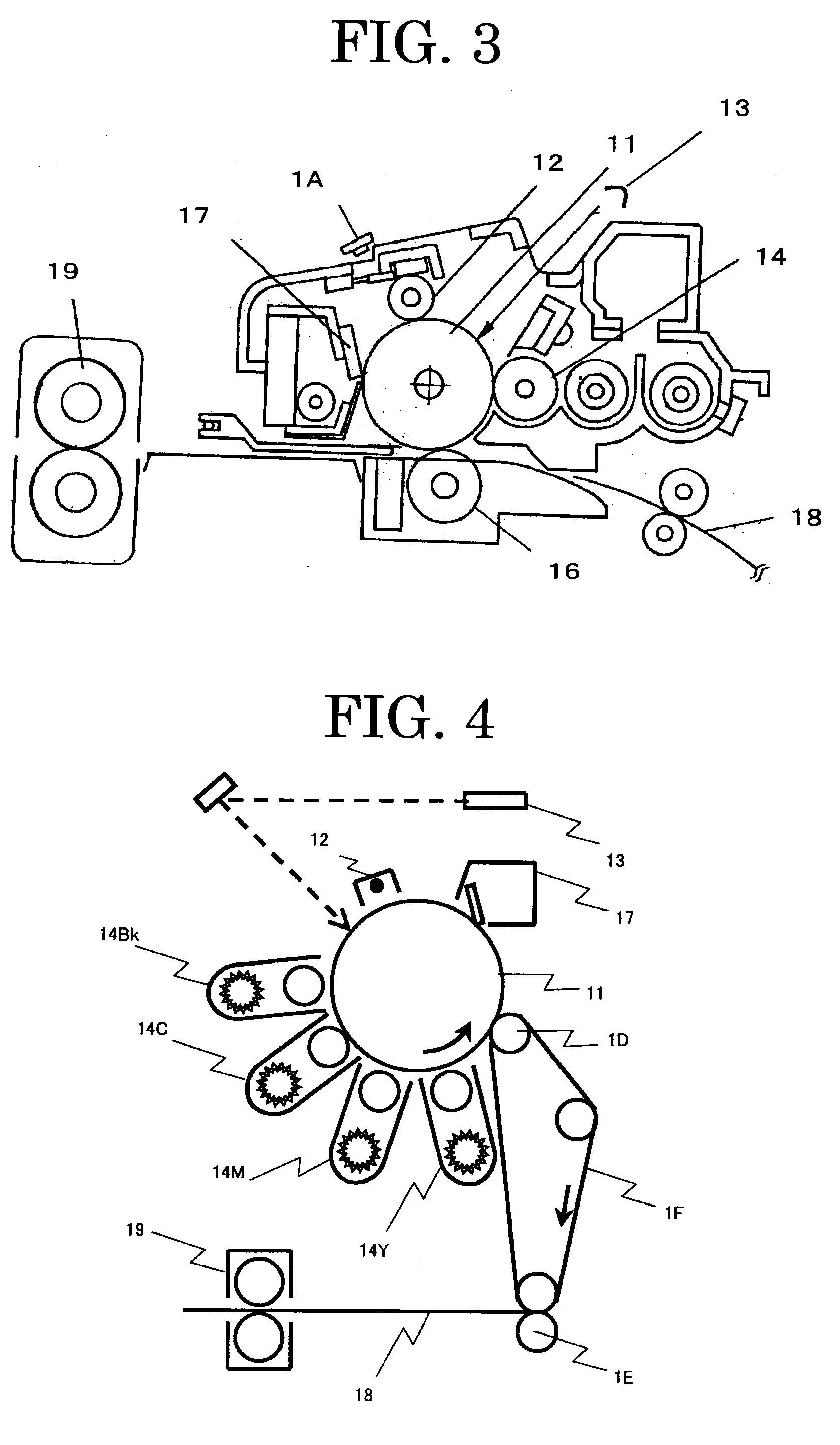
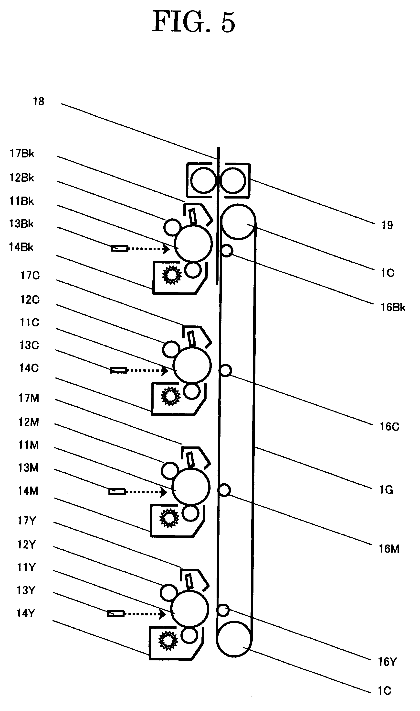
  • Electrophotographic photoconductor, image forming apparatus, and process cartridge
  • Electrophotographic photoconductor, image forming apparatus, and process cartridge
  • Electrophotographic photoconductor, image forming apparatus, and process cartridge

Examples


example 1

[0156]A metal-free phthalocyanine was dispersed under the following composition and condition to prepare a pigment dispersion.

Metal-free phthalocyanine pigment (Fastogen Blue 8120B by 3 partsDainippon Ink and Chemicals, Inc.):Cyclohexanone:97 parts

[0157]These were dispersed in a glass pot of 9 cm diameter using PSZ balls of 0.5 mm diameter for 5 hours at 100 rpm to prepare a pigment dispersion.

[0158]The pigment dispersion was used to prepare a coating liquid for the photosensitive layer of the following composition:

The pigment dispersion:60partsThe electron transporting material expressed by the25partsCompound 1-1:The hole transporting material expressed by the25partsCompound 2-1:Z-polycarbonate resin (Panlite TS-2050 by Teijin50partsChemicals, Ltd.):Silicone oil (KF50 by Shin-Etsu Chemical Co., Ltd.):0.01partsTetrahydrofuran:350parts

[0159]The coating liquid for the photosensitive layer was coated on an aluminum drum having 30 mm diameter and 340 mm length by dip coating and dried a...

example 2

[0160]A photoconductor was produced in the same manner as in the Example 1, except that a titanyl phthalocyanine prepared by the following synthesis example was used instead of the metal-free phthalocyanine pigment (Fastogen Blue 8120B by Dainippon Ink and Chemicals, Inc.) used in the Example 1. (hereinafter referred to as Photoconductor 2).

[0161]A pigment was prepared in accordance with the method disclosed in JP-A No. 2001-19871. More specifically, 29.2 g of 1,3-diiminoisoindoline was mixed with 200 ml of sulfolane, and 20.4 g of titanium tetrabutoxide was added dropwise to the mixture under nitrogen flow. Thereafter, the resultant mixture was gradually heated to 180° C., and allowed to react for 5 hours with agitation while the reaction temperature was kept at 170° C. to 180° C. After cooled down, the resulting precipitate was filtered, washed with chloroform until it became blue, washed with methanol for several times, and then washed with 80° C. hot water for several times, and...

examples 3 to 15

[0171]The photoconductor was produced in the same manner as in the Example 2, except that the electron transporting material and the hole transporting material used in the Example 2 were changed to those shown in Table 3. (hereinafter referred to as Photoconductors 3 to 15).


PUM


Abstract

An electrophotographic photoconductor contains a photosensitive layer and a conductive substrate, wherein the photosensitive layer is disposed on the conductive substrate, and the photosensitive layer is a single layer containing a charge generating material, an electron transporting material expressed by the General Formula (1) and a hole transporting material expressed by the General Formula (2):wherein R1 and R2 independently represent any one of a hydrogen atom, substituted or unsubstituted alkyl group, substituted or unsubstituted cycloalkyl group and substituted or unsubstituted aralkyl group, and R3, R4, R5, R6, R7, R8, R9 and R10 independently represent any one of a hydrogen atom, halogen atom, cyano group, nitro group, amino group, hydroxyl group, substituted or unsubstituted alkyl group, substituted or unsubstituted cycloalkyl group and substituted or unsubstituted aralkyl group; andwherein R11, R12, R13, R14, R17, R18, R19 and R20 each represents a hydrogen atom, halogen atom, alkoxy group, alkyl group which may be substituted or aryl group which may be substituted, R15 and R16 each represents a hydrogen atom, halogen atom, alkyl group, and alkoxy group.

Description

BACKGROUND OF THE INVENTION[0001]1. Field of the Invention[0002]The present invention relates to a single-layer electrophotographic photoconductor containing a photosensitive layer which contains at least a certain electron transporting material and a hole transporting material.[0003]The present invention also relates to a positively charged electrophotographic photoconductor, a positively charged image forming apparatus and a process cartridge using the positively charged electrophotographic photoconductor which contains a single photosensitive layer containing a combination of a certain charge transporting material and an organic sulfur antioxidant, and does not generate an abnormal image such as afterimage even after repeated use.[0004]2. Description of the Related Art[0005]In recent years, developments of information processing system using electrophotographic system are remarkable. Particularly the optical printers in which information is converted to digital signals to be reco...

Claims


Application Information

Patent Timeline
IPC IPC(8): G03G5/06
CPCG03G5/051G03G5/0614G03G5/0696G03G5/0661G03G5/0668G03G5/0651G03G5/061443G03G5/06147G03G5/061473Y10S430/103
Inventor SHIMOYAMA, KEISUKEKURIMOTO, EIJIKAWAMURA, SHINICHI
Owner RICOH KK
Learn More