Vacuum envelope and electron emission display using the vacuum envelope

Inactive Publication Date: 2007-10-25
SAMSUNG SDI CO LTD
View PDF5 Cites 0 Cited by
  • Summary
  • Abstract
  • Description
  • Claims
  • Application Information

AI Technical Summary

Benefits of technology

[0012]An aspect of the present invention provides a vacuum envelope having spacers of heights configured to reduce or minimize deformations of first and second substrates, the deformations being caused by a compression f

Problems solved by technology

Therefore, the first spacers disposed near the outermost portion of the active area may be in an unstable contact with the black layer.
A quality of light emission is thereby deteriorated.

Method used


Image

  • Vacuum envelope and electron emission display using the vacuum envelope
  • Vacuum envelope and electron emission display using the vacuum envelope
  • Vacuum envelope and electron emission display using the vacuum envelope

Examples


Embodiment Construction

[0028]In the following detailed description, only certain exemplary embodiments of the present invention are shown and described, by way of illustration. As those skilled in the art would recognize, the described exemplary embodiments may be modified in various ways, all without departing from the spirit or scope of the present invention. Accordingly, the drawings and description are to be regarded as illustrative in nature, and not restrictive.

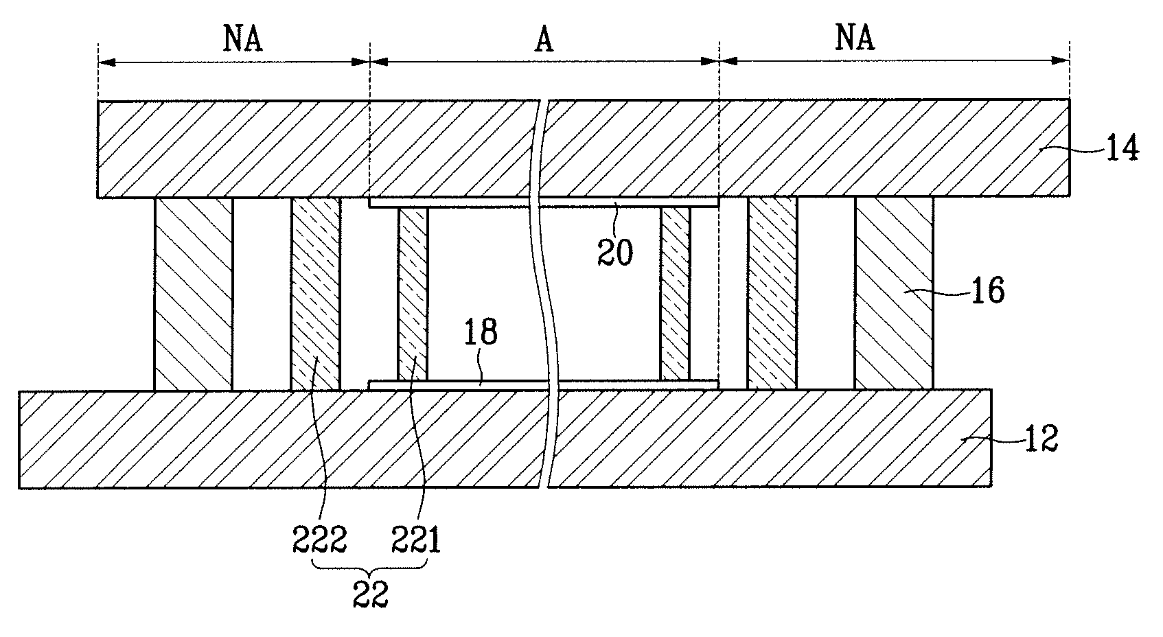
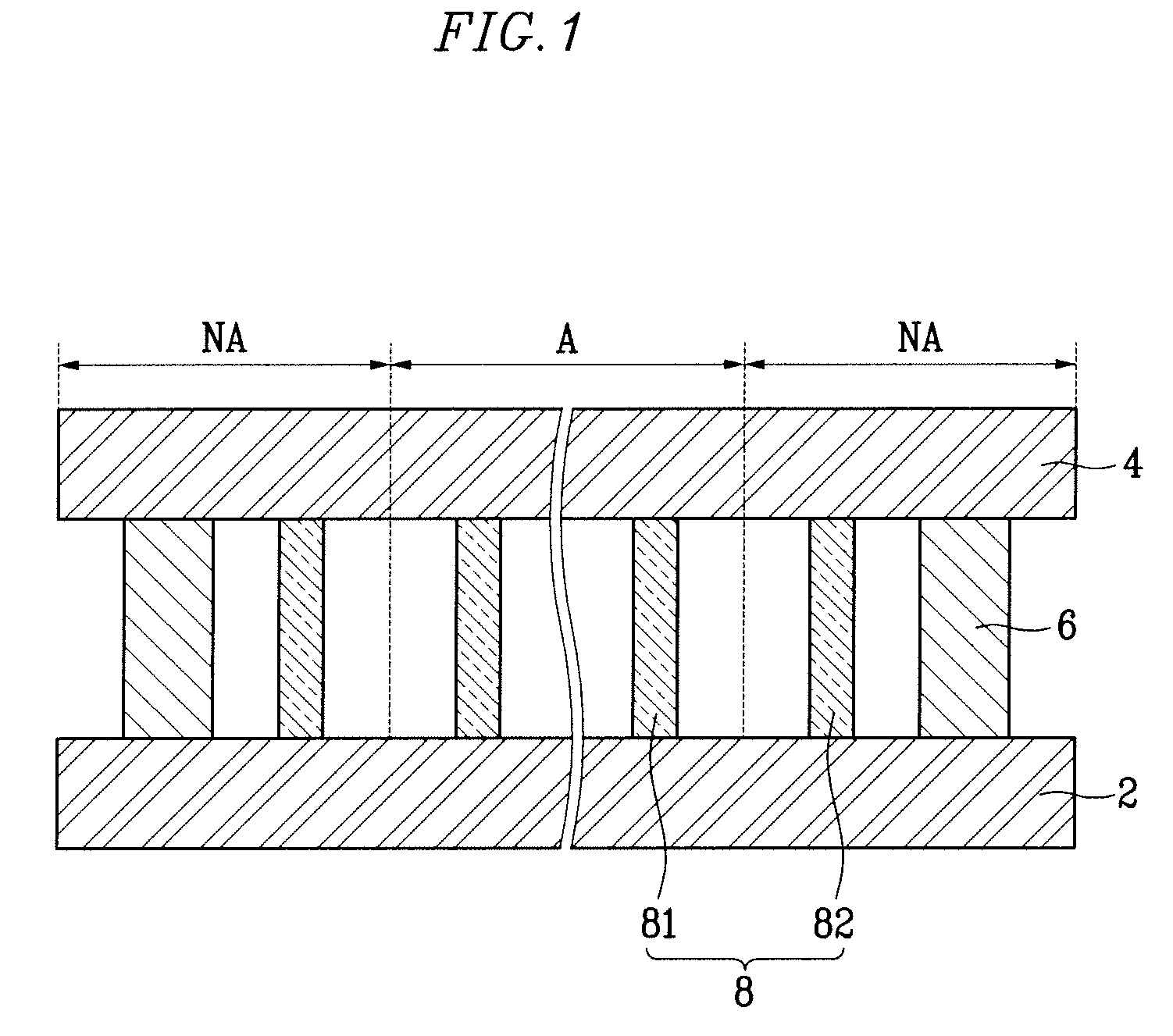
[0029]Referring first to FIG. 1, a vacuum envelope (or chamber) according to an embodiment of the present invention includes first and second substrates 2 and 4 facing each other and spaced apart from each other by a certain (or predetermined) distance. A side member 6 is disposed at peripheries of the first and the second substrates 2 and 4 to seal them together. An interior (between the first and second substrates 2 and 4) of the vacuum envelope is exhausted (or evacuated) such that a vacuum pressure of about 10−6 torr is maintained. That i...


PUM


Abstract

A vacuum envelope and an electron emission display having the vacuum envelope are provided. The vacuum envelope includes a first substrate and a second substrate facing the first substrate. A side member is disposed at peripheries of the first substrate and the second substrate. A first spacer is disposed between the first substrate and the second substrate at an active area of the vacuum envelope, and a second spacer is disposed between the first substrate and the second substrate at a non-active area of the vacuum envelope, the non-active area surrounding the active area. A height of the first spacer is greater than a height of the second spacer.

Description

CROSS-REFERENCE TO RELATED APPLICATION[0001]This application claims priority to and the benefit of Korean Patent Application No. 10-2006-0035821, filed on Apr. 20, 2006, in the Korean Intellectual Property Office, the entire content of which is incorporated herein by reference.BACKGROUND OF THE INVENTION[0002]1. Field of the Invention[0003]The present invention relates to a vacuum envelope and an electron emission display using the vacuum envelope, and more particularly, to spacers disposed in the vacuum envelope to provide a supporting force to the vacuum envelope against an external force.[0004]2. Description of Related Art[0005]A conventional electron emission display includes an array of electron emission elements disposed on a first substrate and a light emission unit disposed on a second substrate. The light emission unit includes phosphor layers and an anode electrode.[0006]The first and the second substrates are sealed together at their peripheries using a side member, and a...

Claims


Application Information

Patent Timeline
IPC IPC(8): H01J63/04H01J1/62
CPCH01J29/864H01J2329/8625H01J31/127H01J1/30H01J31/123
Inventor CHANG, DONG-SULEE, JAE-HOONSEON, HYEONG-RAELEE, JAE-YOUNG
Owner SAMSUNG SDI CO LTD
Why Eureka
Try Eureka