
Water heating systems and methods

Inactive Publication Date: 2007-10-25
A O SMITH
View PDF65 Cites 22 Cited by
  • Summary
  • Abstract
  • Description
  • Claims
  • Application Information

AI Technical Summary

Problems solved by technology

However, several problems have been encountered in the design and development of electronically actuated controllers, and many of the problems are heat related.
Moreover, the temperatures within the controller can reach levels that affect the reliability of the controller's electronics.
However, the heat from the other electronics can affect the temperature readings of the temperature sensor, thereby affecting the reliability of the temperature measurements, if the temperature sensor is in close proximity to the other electronics.
However, increasing the size of the controller is generally undesirable for several reasons, including increasing costs.
Further, water tank manufacturers already have assembly lines in place that may need to be changed, at a relatively high cost, if the design of the water tank is changed to accommodate a larger controller that is electronically actuated.
Moreover, it is generally desirable for the size of an electronically actuated controller to be minimized and, in particular, to be at a size similar to or less than the size of conventional controllers that are mechanically actuated, but such a goal can be difficult to realize without a significant impact to reliability in view of the heat related problems described above.

Method used


Image

  • Water heating systems and methods
  • Water heating systems and methods
  • Water heating systems and methods

Examples


Embodiment Construction

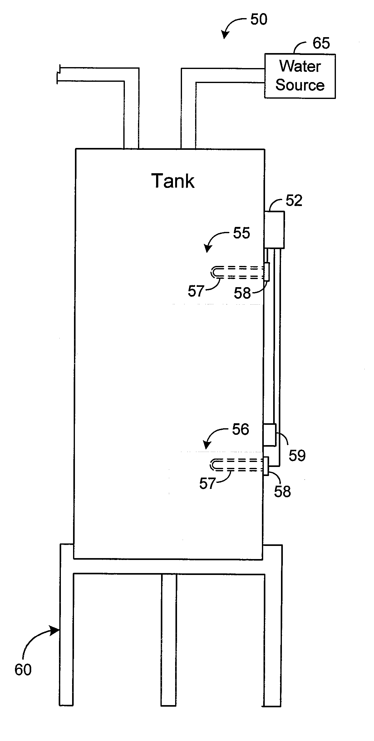
[0045]FIG. 1 depicts a water heating system 50 in accordance with an exemplary embodiment of the present disclosure. In this regard, FIG. 1 depicts an exemplary water heater controller 52 that is electronically actuated and is mounted on a side of a tank 53, although the water heater controller 52 may be positioned at other locations in other embodiments. The system 50 shown by FIG. 1 has two heating elements, referred to as “upper heating element 55” and “lower heating element 56.” Each heating element 55 and 56 comprises an electrically resistive coil 57 that, when activated, emits heat to water or other fluid within the tank 53 and a base 58 that is mounted to a side of the tank 53. The coil 57 is located within the tank 53 and is submerged in the water held by the tank 53. Any known or future-developed heating element may be used to implement either of the heating elements 55 or 56. For many conventional heating elements, the base 58 is screwed into the tank 53 through a hole in...


PUM


Abstract

A water heating system comprises a tank, a sensor holding apparatus, a heating element, a bracket, and a controller that is external to the sensor holding apparatus. The sensor holding apparatus is coupled to an electronic temperature sensor, and the heating element is mounted on the tank. The bracket has a hole and a notch. The heating element passes through the hole, and the sensor holding apparatus is inserted into the notch. The controller is configured to control an operational state of the heating element based on the electronic temperature sensor.

Description

CROSS REFERENCE TO RELATED APPLICATION [0001] This application claims priority to U.S. Provisional Application No. 60 / 786,326, entitled “Water Heating System and Method,” and filed on Mar. 27, 2006, which is incorporated herein by reference. This application also claims priority to U.S. Provisional Application No. 60 / 908,132, entitled “Water Heating Systems and Methods,” and filed on Mar. 26, 2007, which is incorporated herein by reference.RELATED ART [0002] For many decades, water heater controllers have been mechanically actuated. In this regard, at least one temperature sensitive switch is typically mounted on a side of a water tank. Thermal stresses within the switch fluctuate as the temperature of the water within the tank changes. If the temperature of water within a region in close proximity to the switch falls below a threshold, referred to as a “lower set point,” mechanical forces caused by thermal stresses in the switch actuate a mechanical component of the switch thereby ...

Claims


Application Information

Patent Timeline
IPC IPC(8): F24D3/08
CPCF24H9/2014F24H15/414F24H15/296F24H15/174F24H15/37F24H15/225F24H15/281
Inventor PHILLIPS, TERRY G.BULLINGTON, JAMES
Owner A O SMITH
Learn More