
Augmentor variable vane flame stabilization

a variable vane, augmentor technology, applied in continuous combustion chambers, combustion processes, lighting and heating apparatus, etc., can solve the problems of reducing the thrust reducing the life of components required for varying the flameholder position, and creating pressure loss in the airflow of the turbine engine, so as to avoid combustion dynamic instabilities or screech, the effect of reducing the risk of abrasion

Active Publication Date: 2007-10-25
RAYTHEON TECH CORP
View PDF9 Cites 14 Cited by
  • Summary
  • Abstract
  • Description
  • Claims
  • Application Information

AI Technical Summary

Benefits of technology

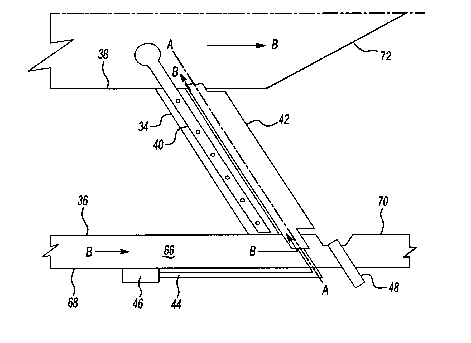
[0007] The augmentor includes vanes radially spaced about the center of the turbine engine. Each vane houses a spraybar to provide fuel to mix with leftover oxygen for a second combustion. A flameholder is located aft of each vane and rotates about an axis also radially spaced about the center of the turbine engine. A linkage connects the flameholder to an actuator to control the rotational position of the flameholder on the axis. Bypass airflow from the fan flows through the bypass duct of the turbine engine. The bypass airflow cools the linkages and the surface of the flameholder.
[0009] The example flameholders of this invention include a variable geometry while providing increased durability.

Problems solved by technology

Flameholders have the disadvantage of creating pressure loss in the airflow of the turbine engine even when the augmentor is not operating.
The pressure loss when the augmentor is not operating decreases the thrust of the turbine engine.
However, due to the excessive heat within the turbine engine the components required for varying the flameholder position have had limited lifespan.
Therefore, variable geometry flameholders have provided limited use in application.

Method used


Image

  • Augmentor variable vane flame stabilization
  • Augmentor variable vane flame stabilization
  • Augmentor variable vane flame stabilization

Examples


Embodiment Construction

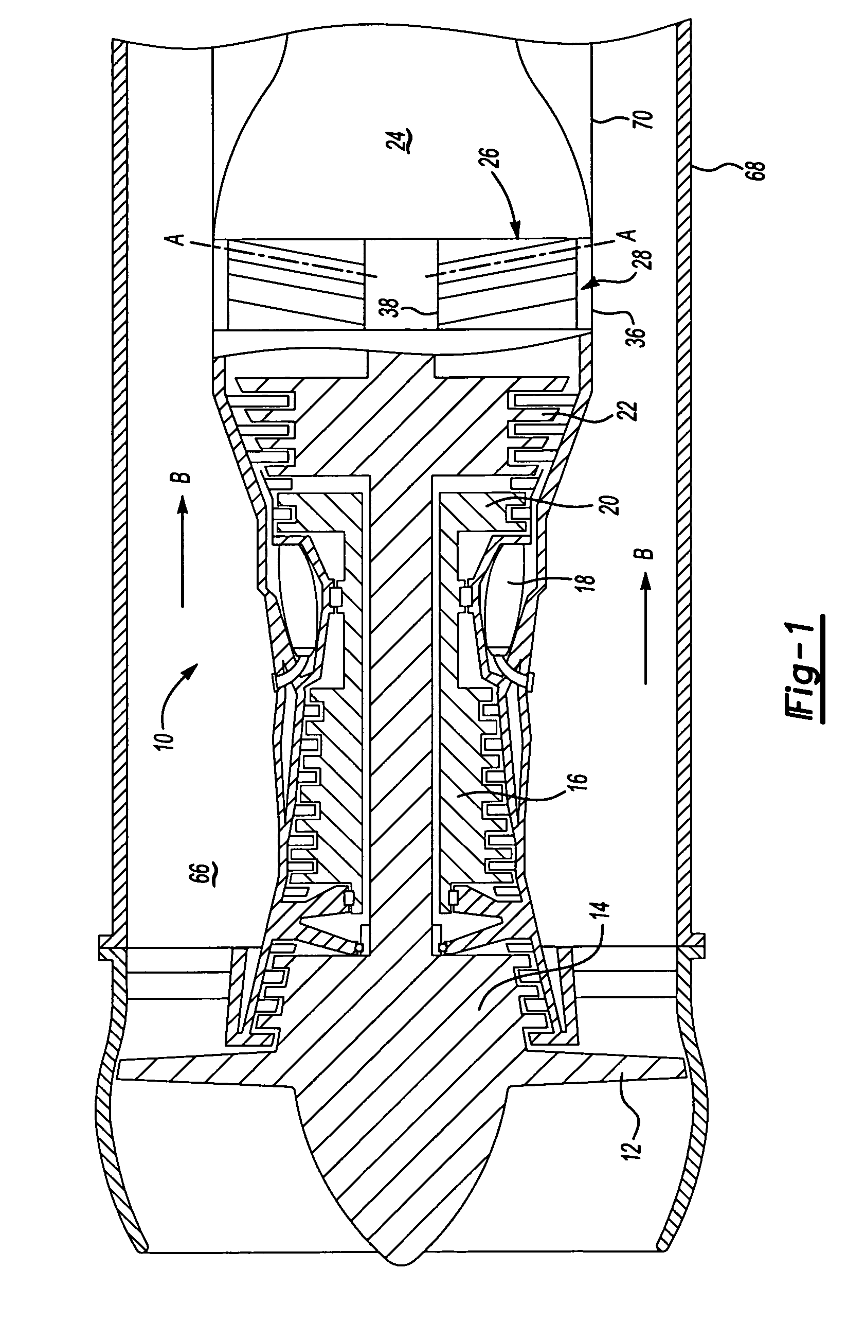
[0018]FIG. 1 is a schematic view of a turbine engine 10. Air is pulled into the turbine engine 10 by a fan 12 and flows through a low pressure compressor 14 and a high pressure compressor 16. Fuel is mixed with the oxygen and combustion occurs within the combustor 18. Exhaust from combustion flows through a high pressure turbine 20 and a low pressure turbine 22 prior to leaving the engine through the exhaust nozzle 24. The example engine 10 includes an afterburner, or augmentor 26. A turbine exhaust case 28 is located in front of the exhaust nozzle 24 and behind the low pressure turbine 22 to house the augmentor 26.

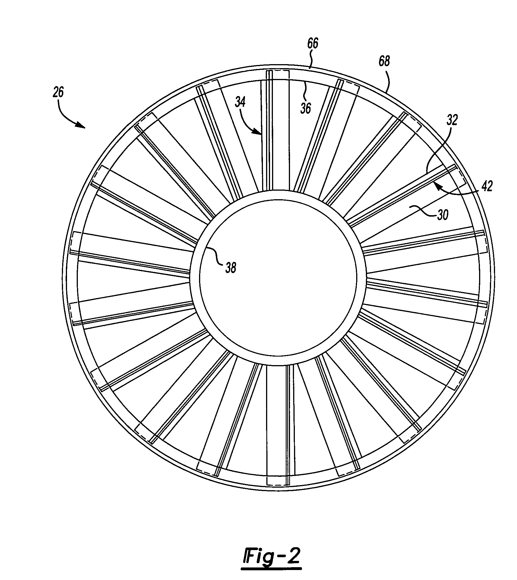
[0019] Referring to FIG. 2 an end view of the augmentor 26 looking upstream into the engine 10 is shown. Air flows into the augmentor 26 at the leading edge 30 and exits at the trailing edge 32. The augmentor 26 includes vanes 34 positioned between a turbine exhaust outer case 36 and a turbine exhaust inner case 38. The vanes 34 are spaced about the turbine exhaust inner...


PUM


Abstract

A flameholder for an augmentor rotates about an axis radially positioned with a turbine engine. The flameholder is in a streamlined position when the augmentor is not operating to minimize pressure loss and radar cross-section and a turbulent position when the augmentor is operating. A linkage connects the flameholder to an actuator to control the rotational position of the flameholder on the axis. Bypass airflow from the fan cools the flameholders and linkages. The length of the linkages can be varied from one flameholder to another to create asymmetric heat release within the augmentor to avoid screech.

Description

BACKGROUND OF THE INVENTION [0001] The invention generally relates to an improved arrangement to provide a variable geometry flameholder in a turbine engine. More particularly, an inventive flameholder provides a streamlined geometry when a turbine engine augmentor is not operating and a “turbulent” geometry when the augmentor is operating. [0002] Turbine engines may have afterburners, or augmentors, located at the rear of the engine upstream of an exhaust nozzle. Augmentors utilize unused oxygen from the turbine engine to obtain a second combustion. The second combustion provides additional thrust from the turbine engine. An augmentor includes flameholders to create low velocity wakes to stabilize combustion in the high velocity turbine engine exhaust. [0003] Flameholders have the disadvantage of creating pressure loss in the airflow of the turbine engine even when the augmentor is not operating. The pressure loss when the augmentor is not operating decreases the thrust of the turb...

Claims


Application Information

Patent Timeline
IPC IPC(8): F02K3/10
CPCF23R3/20F02K3/10
Inventor HAUTMAN, DONALD J.PHILIPPONA, DERK S.
Owner RAYTHEON TECH CORP
Learn More