
Flexible membrane weir

Inactive Publication Date: 2007-10-18
BRIDGESTONE CORP
View PDF0 Cites 0 Cited by
  • Summary
  • Abstract
  • Description
  • Claims
  • Application Information

AI Technical Summary

Benefits of technology

[0010] In the flexible membrane weir according to the invention, even if cracks are caused in a part of the flexible outer bag to leak the fluid from the interior thereof, the deflation of the weir is not caused due to the presence of the flexible inner bag and a certain degree of the weir height can be kept. Therefore, there can be avoided a situation that water stemmed at the upstream side violently flows down to cause serious damage at the downstream side.

Problems solved by technology

The flexible membrane weir may be accidentally deflated due to the breakage of the flexible membrane body based on collision with bounding stone, driftwood, other floating objects and the like.
In this case, the function as the weir is damaged and hence it is also envisaged that a greater amount of water stemmed by the flexible membrane weir violently flows from the upstream side to cause serious damage at the downstream side.
Although the flexible membrane weir was used at a small size in the restricted applications such as agricultural water and the like, the role thereof is recently enlarged to applications such as urban disaster prevention, water space and the like, and hence the size becomes larger and the risk due to the accidental deflation is increasing accompanied therewith.
Even if the double structure is adopted in the flexible membrane weir as disclosed in the above patent document, however, there is still existent a possibility that the damage of the inner tube is caused by the impaling of the driftwood passing through the outer layer rubber (or flexible membrane), cantrip and the like.

Method used


Image

  • Flexible membrane weir
  • Flexible membrane weir
  • Flexible membrane weir

Examples


Embodiment Construction

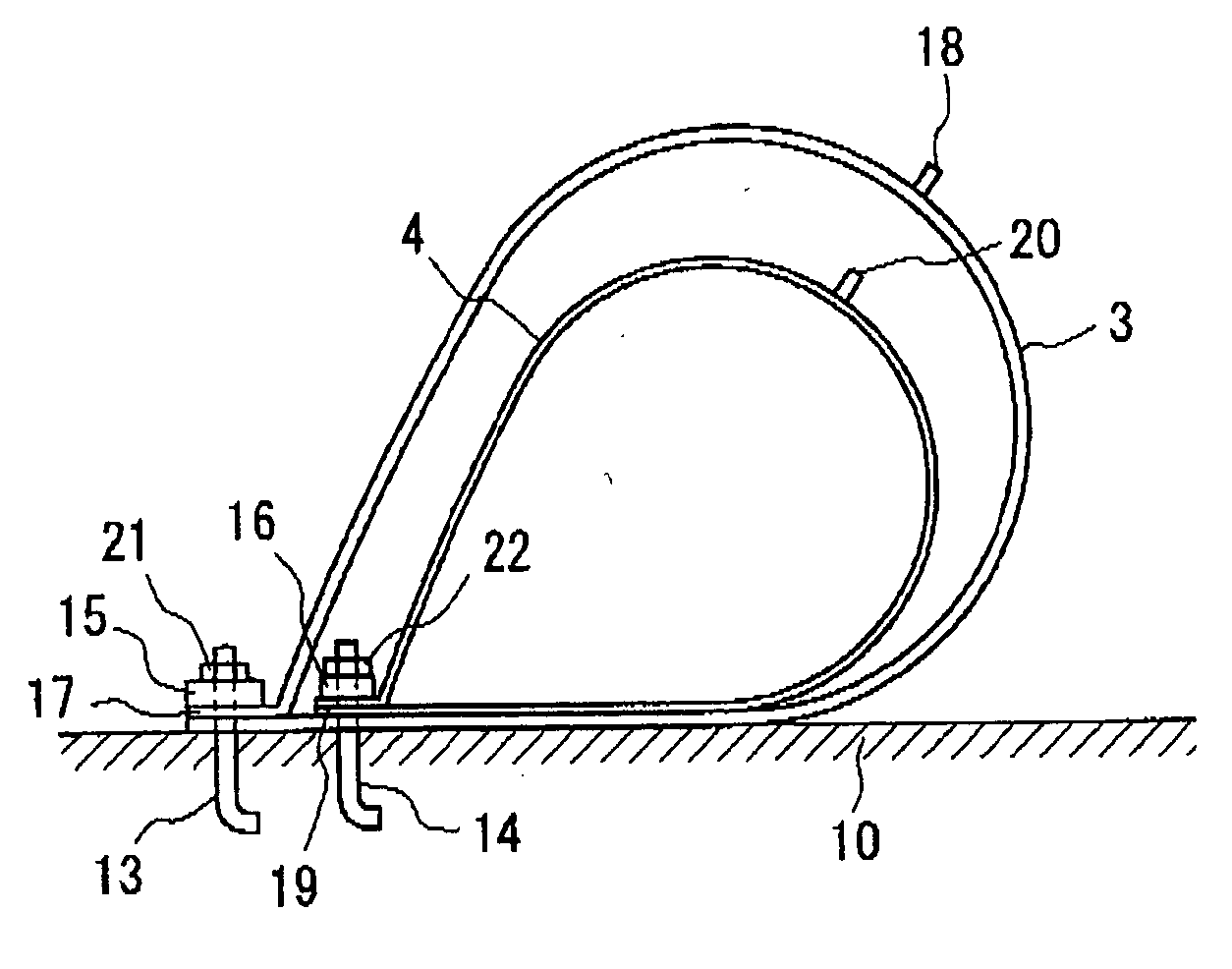
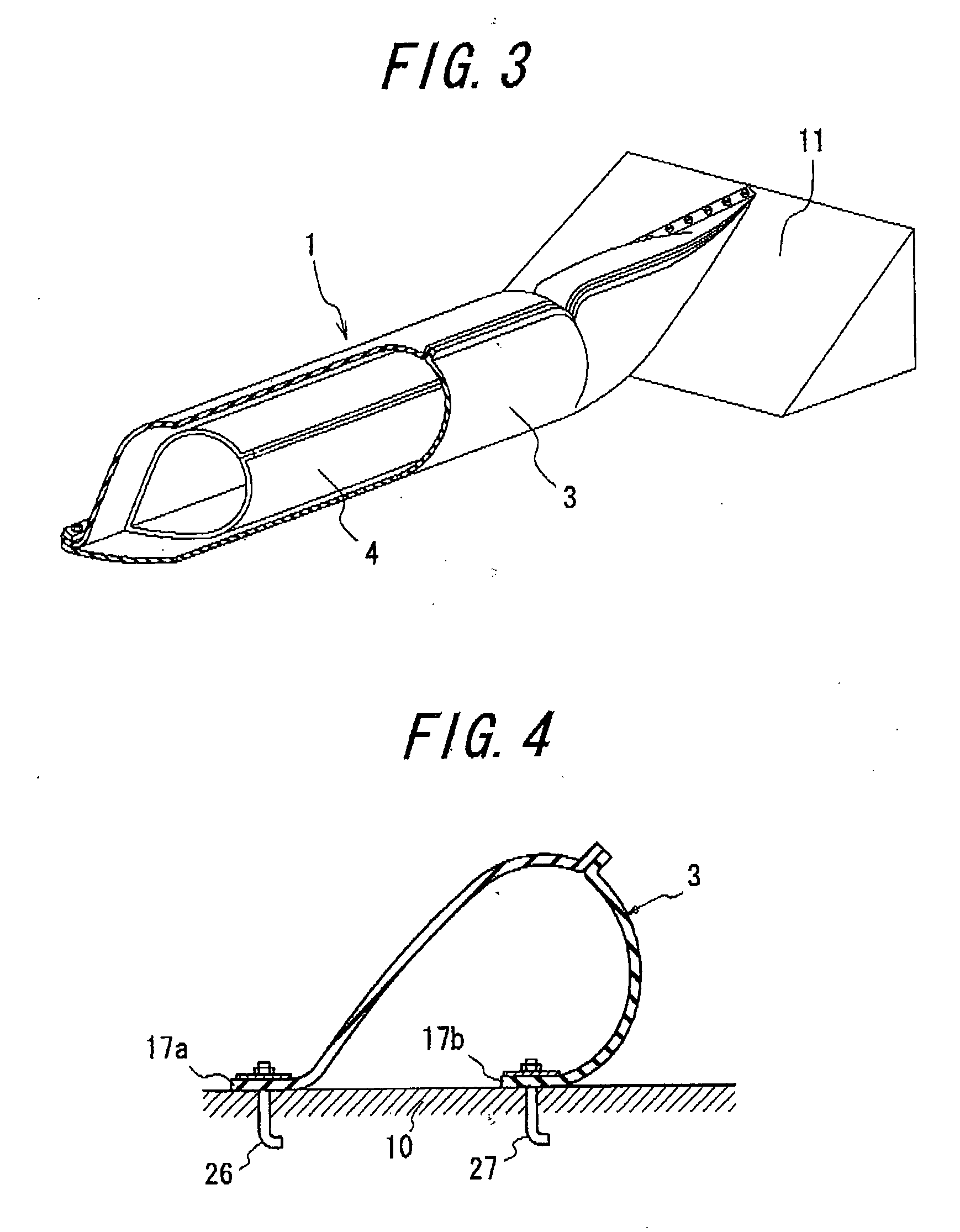
[0020] An embodiment of the invention is explained with reference to the accompanying drawings. FIG. 1 is a front view of the flexible membrane weir according to the first embodiment of the invention, and FIG. 2 is a section view taken along a line A-A of FIG. 1, and FIG. 3 is a perspective view partly shown in section of this flexible membrane weir.

[0021] As shown in FIG. 1, the flexible membrane weir 1 comprises a lengthy flexible outer bag 3 arranged so as to extend in a widthwise direction of a water channel 2 (direction of arrow W) for opening and closing the water channel to intake service water, which inflates through the supply of a fluid such as air, water or the like to the interior thereof and deflates through the drain of the fluid from the interior as shown in FIGS. 2 and 3, and a lengthy flexible inner bag 4 accommodated and arranged in the interior of the flexible outer bag 3 and capable of arranging another fluid supply and drain.

[0022] In FIGS. 1-3, two rows of an...


PUM


Abstract

A flexible membrane weir comprises a lengthy flexible outer bag arranged in a widthwise direction of a water channel and provided with a fluid supply-drain means, and a lengthy flexible inner bag accommodated and arranged in the interior of the flexible outer bag and provided with another fluid supply-drain means.

Description

BACKGROUND OF THE INVENTION [0001] 1. Field of the Invention [0002] This invention relates to a flexible membrane weir inflating or deflating by supply or drain of a fluid such as air, water or the like, and more particularly to a flexible membrane weir not completely keeping the function as a weir even if abnormal state is caused in a part of the weir. [0003] 2. Description of the Related Art [0004] Recently, a flexible membrane weir called as a rubber dam inflating and deflating by the supply and drain of a fluid such as air water or the like is widely used because it is simple in the laying and cheap in the cost. The flexible membrane weir is arranged on a river bed or the like so as to direct a longitudinal direction of the flexible membrane body to a widthwise direction of a water channel and inflated by supplying the fluid to an interior of the flexible membrane body to stem water in the water channel. Then, it is deflated by draining the fluid from the interior of the flexibl...

Claims


Application Information

Patent Timeline
IPC IPC(8): E02B7/20E02B7/02
CPCE02B7/005
Inventor AKIYAMA, HITOSHI
Owner BRIDGESTONE CORP
Learn More