
Stereoscopic electro-optical device and electronic apparatus with cross-talk correction

a technology of applied in the field of stereoscopic electrooptical devices and electronic devices with crosstalk correction, can solve the problems of insufficient suppression of crosstalk, limited interval in which the user can actually see the image, and difficulty in clearly recognizing the image as a stereoscopic image, etc., to achieve the effect of improving the brightness of the displayed imag

Inactive Publication Date: 2015-10-27
SEIKO EPSON CORP
View PDF26 Cites 0 Cited by
  • Summary
  • Abstract
  • Description
  • Claims
  • Application Information

AI Technical Summary

Benefits of technology

The invention improves the brightness of a displayed image while suppressing the intermixing of right-eye and left-eye images. It uses two correction images, one for brightness and one for crosstalk suppression. The first correction image data is generated using a table, providing high-speed response. The second correction image data is generated based on a table, reducing crosstalk. The invention offers improved design flexibility and reduced crosstalk.

Problems solved by technology

With this scheme, crosstalk, in which the right-eye image and the left-eye image become intermixed, occurs during an interval in which one of the right-eye image and the left-eye image is rewritten by the other side; when a viewer sees the image, it is difficult for him or her to clearly recognize that image as a stereoscopic image.
For this reason, crosstalk cannot be sufficiently suppressed even with the aforementioned correction.
However, with the technique disclosed in JP-A-2009-25436, the interval in which the user can actually see the image is limited to the latter halves of the respective right unit interval and left unit interval (that is to say, is limited to be approximately half of the interval).
Accordingly, there is a problem in that it is difficult to ensure sufficient brightness in the displayed image.

Method used


Image

  • Stereoscopic electro-optical device and electronic apparatus with cross-talk correction
  • Stereoscopic electro-optical device and electronic apparatus with cross-talk correction
  • Stereoscopic electro-optical device and electronic apparatus with cross-talk correction

Examples


first embodiment

1. First Embodiment

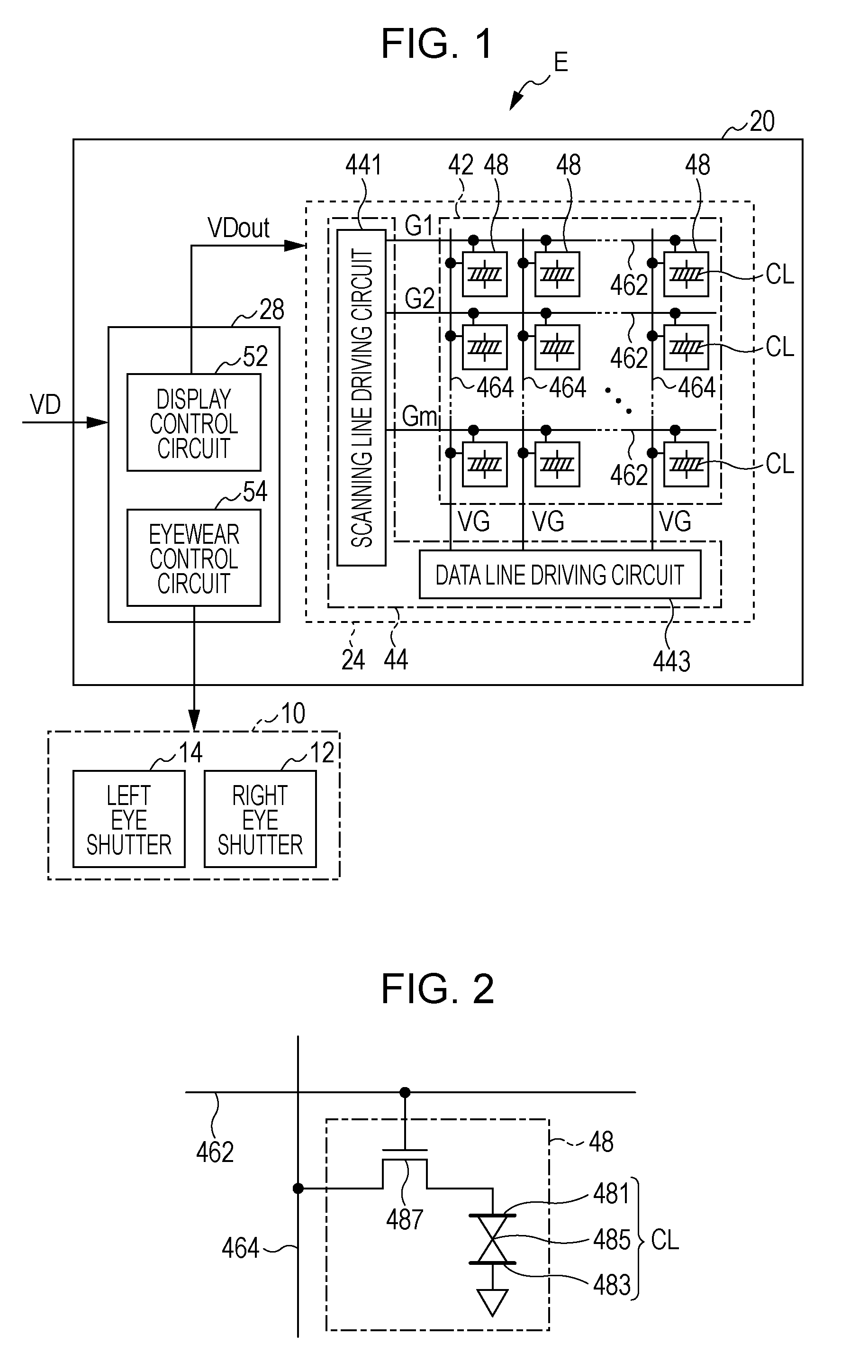
[0034]FIG. 1 is a block diagram illustrating an electronic apparatus E according to a first embodiment of the invention. The electronic apparatus E displays stereoscopic images, which are sensed stereoscopically by a viewer, using a frame-sequential scheme. As shown in FIG. 1, the electronic apparatus E includes stereoscopic eyewear 10 and an electro-optical device 20.

[0035]The stereoscopic eyewear 10 shown in FIG. 1 is an eyeglass-shaped implement donned by a viewer when viewing stereoscopic images displayed by the electro-optical device 20, and is configured so as to include a right-eye shutter 12 located in front of the right eye of the viewer and a left-eye shutter 14 located in front of the left eye of the viewer. The right-eye shutter 12 and the left-eye shutter 14 are controlled so as to take on an open state that allows emitted light to pass through and a closed state that blocks emitted light. For example, liquid-crystal shutters that change from the open...

second embodiment

2. Second Embodiment

[0058]In the aforementioned first embodiment, the second correction image data generation unit 524 is compliant with a single type of stereoscopic eyewear 10. As opposed to this, the electronic apparatus E according to the second embodiment is compliant with a plurality of types of stereoscopic eyewear 10, and aside from the display control circuit 52 being replaced with a display control circuit 52A as shown in FIG. 8, has the same configuration as the electronic apparatus E according to the first embodiment.

[0059]In the display control circuit 52A, the second correction table LUT 2 includes k (where k is an integer of 2 or more) individual correction tables LUT 21, LUT 22, and so on up to LUT 2k. The k second correction tables LUT 21, LUT 22, and so on up to LUT 2k correspond to each of k types of stereoscopic eyewear 10. An identification signal ID that identifies the type of the stereoscopic eyewear 10 is sent from the stereoscopic eyewear 10. A control unit ...

third embodiment

3. Third Embodiment

[0062]In the aforementioned first embodiment, the second correction image data generation unit 524 includes the second correction table LUT 2, which corresponds to a certain temperature. As opposed to this, an electronic apparatus E according to the third embodiment includes individual correction tables LUT 31, LUT 32, and so on up to LUT 3k, which correspond to a plurality of temperatures.

[0063]FIG. 9 illustrates a display control circuit 52B according to the third embodiment. In the display control circuit 52B, the second correction table LUT 2 includes k (where k is an integer of 2 or more) individual correction tables LUT 31, LUT 32, and so on up to LUT 3k. The k individual correction tables LUT 31, LUT 32, and so on up to LUT 3k correspond to each of k types of temperatures.

[0064]A temperature sensor 527 detects a temperature and supplies a temperature signal indicating the detected temperature to a control unit 521B. The control unit 521B then generates a se...


PUM


Abstract

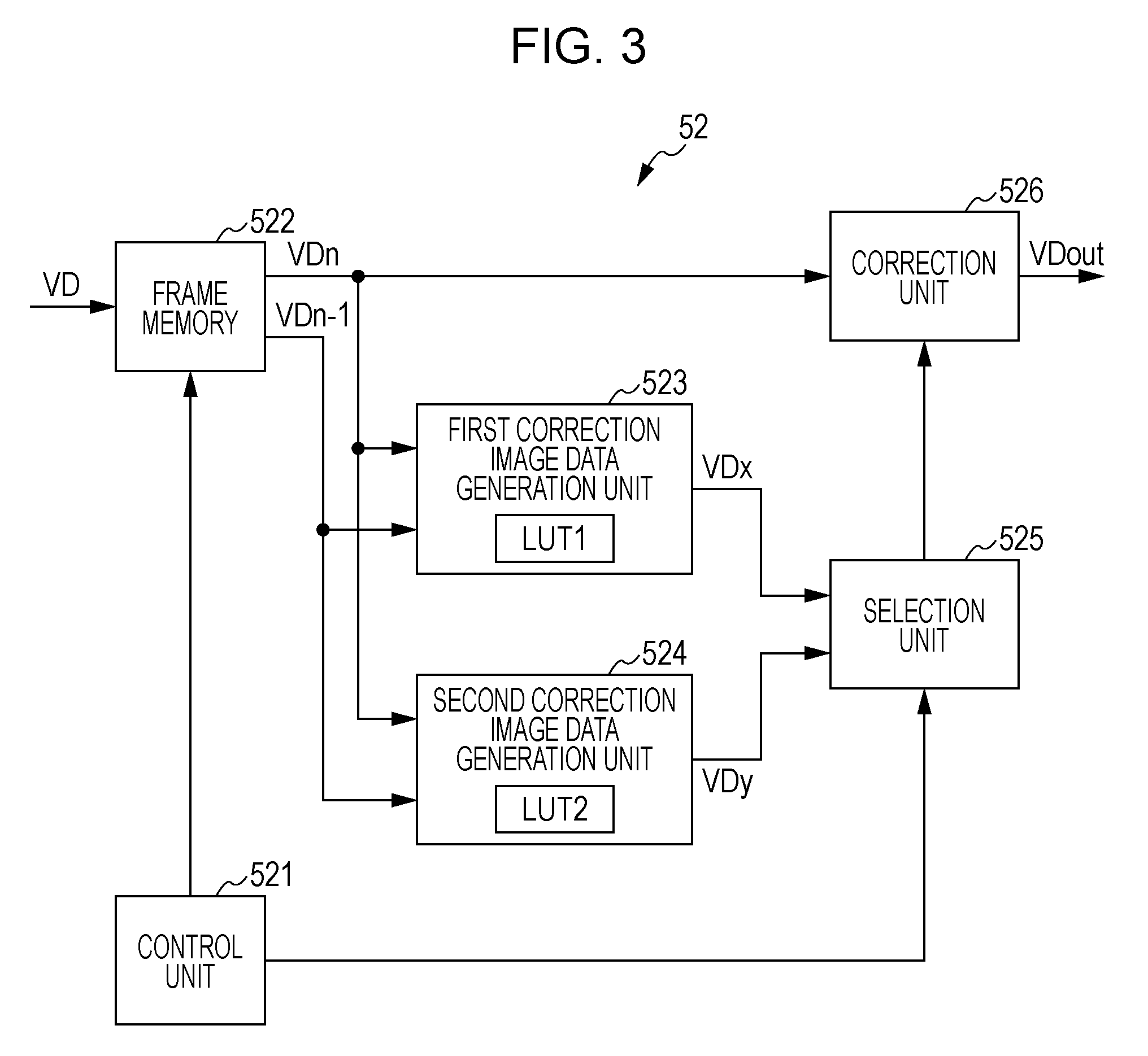
A display control circuit includes: a frame memory; a first correction image data generation unit that generates first correction image data that corrects a response characteristic of an electro-optical element; a second correction image data generation unit that generates second correction image data that corrects the intermixing of a right-eye image and a left-eye image; a selection unit that selects the first correction image data in a first field and the second correction image data in a second and subsequent fields; and a correction unit that generates output image data by correcting the first image data.

Description

BACKGROUND[0001]1. Technical Field[0002]The present invention relates to techniques for displaying right-eye images and left-eye images that have been made disparate from each other so that a viewer senses a stereoscopic image.[0003]2. Related Art[0004]In the past, a frame-sequential stereoscopic scheme that displays right-eye images and left-eye images alternately through time division has been proposed. With this scheme, crosstalk, in which the right-eye image and the left-eye image become intermixed, occurs during an interval in which one of the right-eye image and the left-eye image is rewritten by the other side; when a viewer sees the image, it is difficult for him or her to clearly recognize that image as a stereoscopic image.[0005]In order to solve this problem, JP-A-2001-54143, for example, discloses a technique in which crosstalk from a left-eye image is corrected in advance when a right-eye image is displayed and crosstalk from a right-eye image is corrected in advance wh...

Claims


Application Information

Patent Timeline
Patent Type & Authority Patents(United States)
IPC IPC(8): H04N13/04G02B27/22H04N13/00
CPCG02B27/2228G02B27/2264H04N13/0018H04N13/0033H04N13/0438H04N13/0497G02B30/24G02B30/34H04N13/122H04N13/144H04N13/341H04N13/398
Inventor YOSHIMOTO, HIROSHI
Owner SEIKO EPSON CORP
Learn More