
Implantable sensor

a sensor and implant technology, applied in the field of implantable sensors, can solve problems such as implant loss, osteolytic lesions, and need for revision surgery

Inactive Publication Date: 2007-10-11
WARSAW ORTHOPEDIC INC
View PDF78 Cites 50 Cited by
  • Summary
  • Abstract
  • Description
  • Claims
  • Application Information

AI Technical Summary

Problems solved by technology

This debris may lead to osteolytic lesions, implant loosing, and possibly the need for revision surgery.
Further, in soft tissue repairs, such as ACL reconstruction, the tissue may have problems with graft incorporation or failure to fully heal the defect.

Method used


Image

  • Implantable sensor
  • Implantable sensor
  • Implantable sensor

Examples


Embodiment Construction

[0040] For the purposes of promoting an understanding of the principles of the present invention, reference will now be made to the embodiments illustrated in the drawings, and specific language will be used to describe the same. It will nevertheless be understood that no limitation of the scope of the invention is intended. Any alterations and further modifications in the described devices, instruments, methods, and any further application of the principles of the invention as described herein are contemplated as would normally occur to one skilled in the art to which the invention relates.

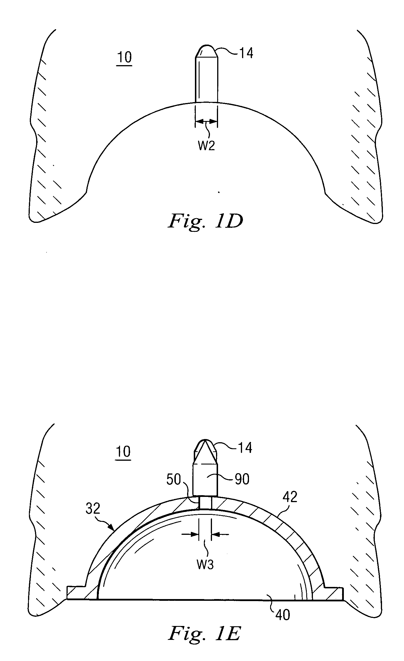
[0041] Referring now to FIGS. 1A-1E, shown therein is an implantable sensor 90 for monitoring changes in bone density in the bony areas 10, 20 around a hip implant or prosthesis 30 according to one aspect of the present invention. In particular, the sensor 90 is configured for detecting the onset of osteolysis and the development of osteolytic lesions. The hip prosthesis 30 being monitored inclu...


PUM


Abstract

An implantable sensor for detecting changes in tissue density is disclosed. The implantable sensor includes a transducer adapted for detecting indicators of tissue density. The implantable sensor includes memory for storing data corresponding to the tissue density indicators detected by the sensor. A telemetry circuit is configured for transmitting the tissue density data outside of the body.

Description

FIELD OF THE INVENTION [0001] The present invention is directed to improved instrumentation and methods for measuring tissue density. More particularly, in one aspect the present invention is directed to an implantable sensor for detecting changes in tissue density. BACKGROUND OF THE INVENTION [0002] The present invention relates to the assessment of tissue density. The invention may have particularly useful application in the assessment of tissue density as it relates to total joint replacement surgeries including the implantation of hip, knee, shoulder, ankle, spinal and wrist prostheses. The invention may also have particularly useful application in the assessment of tissue density as it relates to soft tissue repairs such as ACL reconstruction or meniscal reconstruction, for example. [0003] Joint prostheses are usually manufactured of durable materials such as metals, ceramics, or hard plastics and are affixed to articulating ends of the bones of the joint. Joint prostheses usua...

Claims


Application Information

Patent Timeline
Patent Type & Authority Applications(United States)
IPC IPC(8): A61B8/00
CPCA61B5/076A61B5/4509A61B5/4528A61B5/6882A61B8/565A61B7/006A61B8/0875A61B8/4472A61B8/56A61B7/005
Inventor DONOFRIO, WILLIAM T.NYCZ, JEFFREY H.CINBIS, CANMORRISON, MATTHEW M.DRAPEAU, SUSAN J.
Owner WARSAW ORTHOPEDIC INC
Learn More