Modular personal defense device

a personal protection device and module technology, applied in racket sports, gymnastics, clubs, etc., can solve the problems of affecting the movement of security personnel, little has been done over the years to improve such handheld impact weapons, and the audible and visual impression generated by the electrical arc across the contacts is quite intimidating, so as to achieve disorientation, emotional changes, and/or other effects in persons

Inactive Publication Date: 2007-10-11
STETHEM KENNETH J
View PDF47 Cites 41 Cited by
  • Summary
  • Abstract
  • Description
  • Claims
  • Application Information

AI Technical Summary

Benefits of technology

[0045] The electrical stun module may be interchanged with other modules that are essentially externally identical physically to one another. One such module may incorporate superbright LED lighting components to temporarily blind an assailant. The lighting may be caused to flicker rapidly, an effect that is known to produce disorientation, emotional changes, and / or other effects in persons. Another module may be used to produce a piercing sound to temporarily dissuade an assailant or threat. Still another module may be installed axially or radially to actuate an irritant spray canister or the like (e.g., pepper spray or Mace®, etc.), thus providing a chemical deterrent. The dual actuating switches provided enable a user to actuate the various functions, particularly the electrical stun and light circuitry, in a momentary or continuously actuated manner. The device may also be removably attached to a lethal weapon, e.g., an M-16 rifle, by means of a conventional attachment mechanism.

Problems solved by technology

Very little has been done over the years to improve such handheld impact weapons, other than changing the mass of different portions to impart greater force upon impact.
Such devices are quite effective in subduing a threatening individual, or even a small crowd, as the audible and visual impression generated by the electrical arc across the contacts is quite intimidating.
For example, it has been found that extremely bright light focused relatively closely in the eyes of a potentially threatening individual, particularly in relatively darkened areas, greatly reduces the threat due to the temporary obscuration of the threatening individual's vision.
An obvious example is where the assailant has a weapon, and it is not desirable to approach the individual close enough to contact him or her with an impact baton or electrical stun device.
Obviously, the weight and bulk of such multiple systems would greatly impede the movement of such security personnel and could put such security personnel at greater risk due to the physical handicap imposed by such an excessive load of equipment.
In any event, the device of the Burton '549 U.S. Patent is quite long and thin, and is not adapted for use as an impact weapon in addition to its electrical prod function.
However, Hansen et al. do not disclose a relatively massive barrel portion for use as an impact weapon, nor other means (blades, etc.) for such impact function.
In any case, Mongan does not provide any means for using his device as an impact weapon, and further teaches away from the first embodiment of the present stun device by providing an open circuit until one of the contacts is pushed in.
If an assailant or threat grabs the barrel of the stick, he or she applies pressure to the guard, causing the guard to retract and the spikes to be exposed.
Larsen et al. disclose a transistorized circuit for controlling electrical power in their nightstick, but no means of providing alternating current to produce a continuing series of discharges is disclosed.
Also, while Shimizu provides an axially placed light in one end of his nightstick, the light cannot be directed radially from the side of the device.
Also, Jordan does not provide any form of lighting means, impact enhancing means, or interchangeable modules for different functions with his stick.
Such size and weight is not suitable for use as an impact weapon, nightstick, or billy club, whereas the present device provides sufficient mass and size to be useful as an impact weapon as well.
Allen does not disclose any form of lighting for his prod device.
No means of producing or dispensing a high voltage electrical current or shock is provided by Mains for his light and baton combination.
Yanez includes a light with his electrical discharge apparatus, but the light is not intended to provide any real degree of illumination for the person using the device.
Moreover, Ward does not provide any form of lighting with his device.
LaCroix also provides a light having sufficient intensity to temporarily blind a potential assailant, rather than to provide any useful illumination for the user of the device.
The lateral extension of the LaCroix device does not facilitate its use as an impact weapon, as provided by the generally cylindrical configuration of the present device.
Moreover, de Anda et al. do not disclose any form of lighting with their device, and the concealed electrical contacts cannot provide a visible display of electrical discharge to dissuade a potential attacker.
The physical configuration of the Murray device does not enable it to be used as an impact weapon, e.g., nightstick, etc., as can the present device.
Thus, the electrical device cannot be controlled once it leaves the weapon.
Moreover, while Chaput provides additional electrodes along the sides of the impact sleeve, he does not provide any additional ribs or blades to increase the effectiveness of the device as an impact weapon, as provided by the present personal defense device.
The Chang assembly cannot be used as an impact weapon, as it is relatively short and compact, with the operating switches located at the approximate midpoints along the opposite sides thereof.
Moreover, the hollow telescoping tubes of the Lin device do not appear to provide sufficient strength for use as an impact weapon (baton, etc.), and Lin makes no disclosure or claim of such function for his device.
However, the relatively short length of the McNulty stun device is not suitable for use as an impact weapon or baton, and no lighting means is provided by McNulty for his device.

Method used


Image

  • Modular personal defense device
  • Modular personal defense device
  • Modular personal defense device

Examples


Embodiment Construction

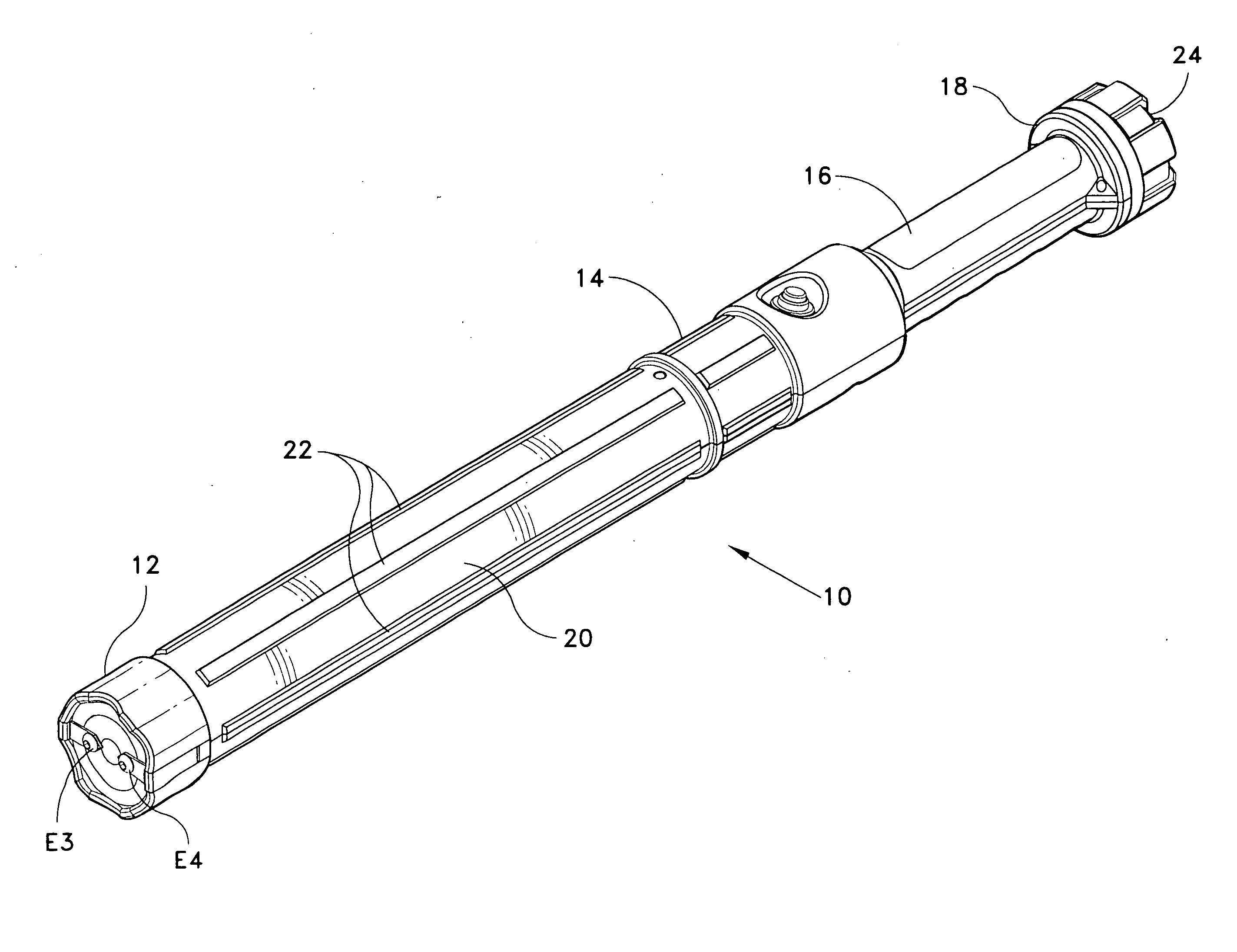
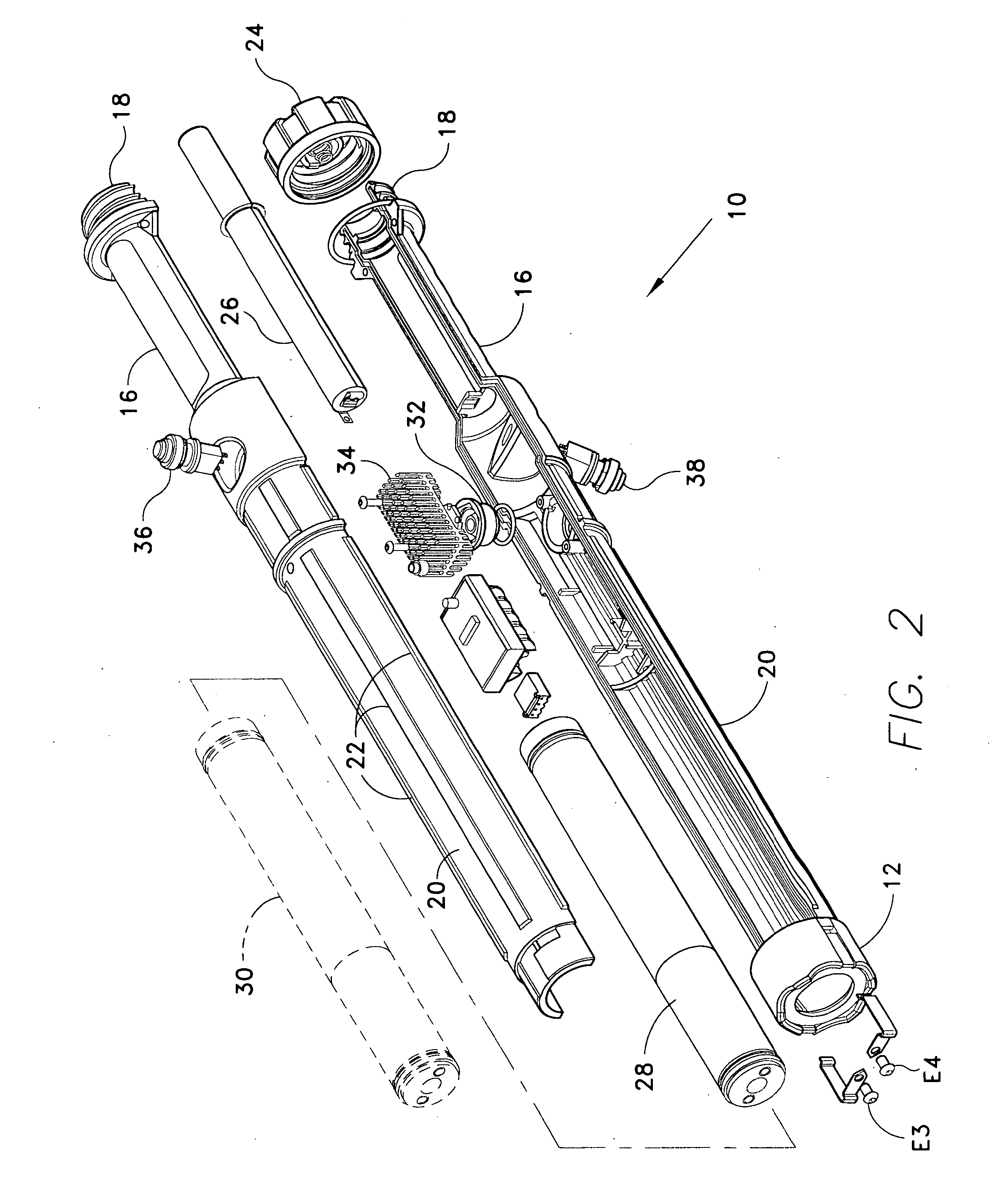
[0056] The present invention comprises various embodiments of a personal defense device. My prior U.S. Pat. Nos. 6,643,114, issued Nov. 4, 2003, and 6,791,816, issued Sep. 14, 2004, both of which are hereby incorporated by reference, describe improvements in baton-style personal defense devices. The present application describes further improvements in baton-style personal defense devices in which various defensive output modules providing various defensive or deterrent effects or functions may be installed interchangeably with one another. The various output modules are enclosed within a rigid, hard baton that serves as an impact weapon, i.e., a nightstick like device.

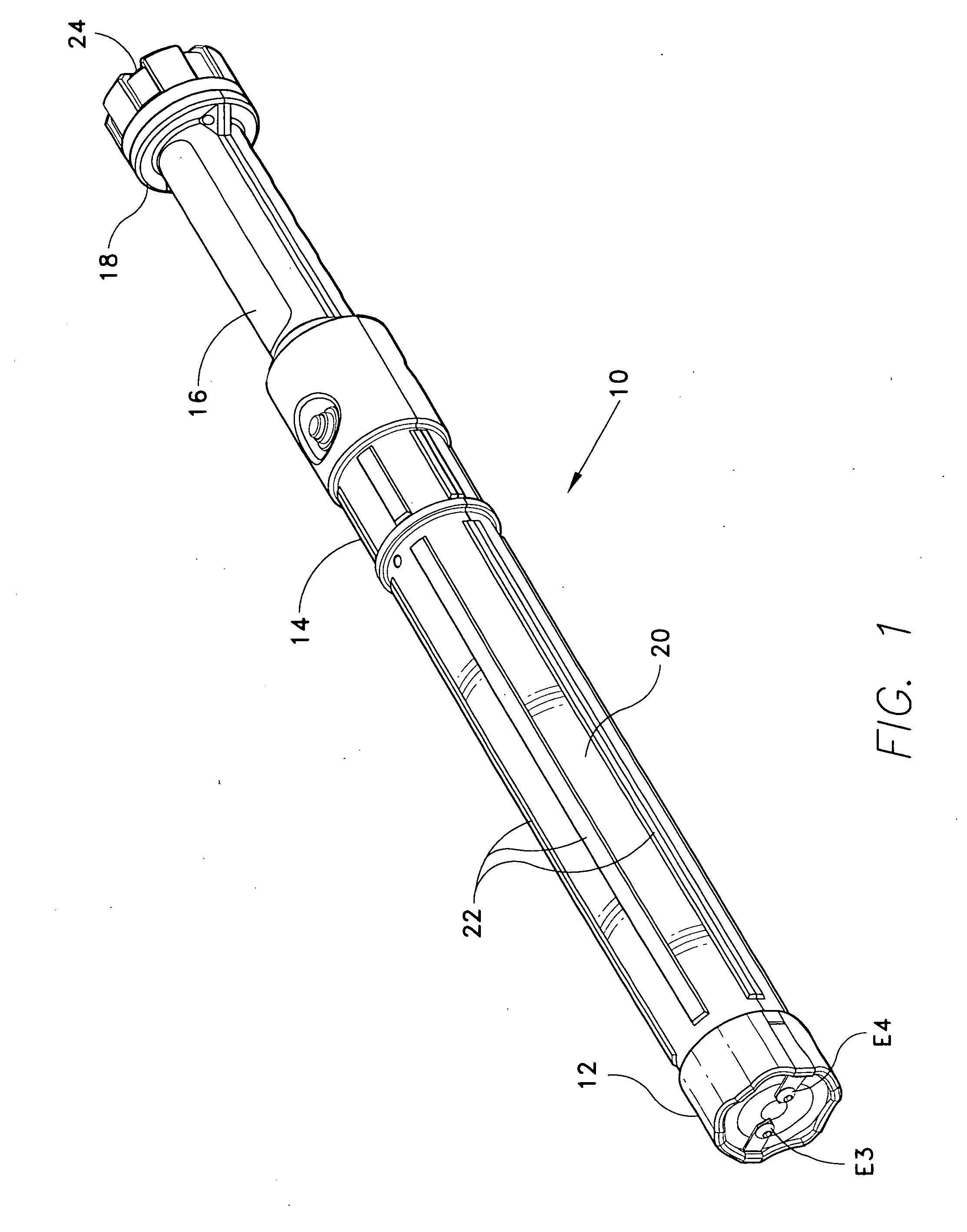
[0057]FIG. 1 of the drawings provides a perspective view of a personal defense device 10 having an electrical stun output end cap 12 installed thereon. The defense device 10 basically comprises a hard, rigid, elongate, hollow baton 14 having a concentric handle portion 16 and handle end 18, with an impact portion 20 ...


PUM


Abstract

The modular personal defense device is a hard, rigid, elongate baton that is capable of imparting impact force to an assailant or threat. The exterior may include a series of strengthening ribs, which may also impart further damage to an assailant. The interior is an essentially hollow cylinder configured to accept one of a series of modules. The modules are essentially externally physically identical, but include different electronic circuitry and mechanisms to provide different functions. A silicone controlled rectifier (SCR) electronic stun circuit is provided by one module, for imparting a stunning electrical shock and dissuading an assailant(s) due to the electrical arc produced. Another module produces an extremely bright light either continuously or in rapid pulses, to blind and disorient an assailant. Yet another module produces a piercing sound, while still other modules may be fitted axially or radially to the device to transmit an irritant spray.

Description

REFERENCE TO RELATED PATENT APPLICATIONS [0001] This application is a continuation-in-part of U.S. patent application Ser. No. 10 / 938,553 filed on Sep. 13, 2004, which is a continuation of U.S. patent application Ser. No. 10 / 375,075 filed on Feb. 28, 2003, which issued Sep. 14, 2004 as U.S. Pat. No. 6,791,816, and which is a continuation-in-part of U.S. patent application Ser. No. 10 / 084,972, filed on Mar. 1, 2002, which issued Nov. 4, 2003 as U.S. Pat. No. 6,643,114.BACKGROUND OF THE INVENTION [0002] 1. Field of the Invention [0003] The present invention relates generally to nonlethal weaponry and / or personal protective devices. More particularly, the present device comprises a rigid, elongate nightstick or club configuration having a series of interchangeable modules for affecting the senses of an assailant. The device may be used conventionally as a handheld impact weapon, i.e., nightstick or the like, and / or may be used with various interchangeable modules as a high voltage stun...

Claims


Application Information

Patent Timeline
IPC IPC(8): A63B59/00
CPCF41B15/04F41H13/0087F41H13/0018F41H9/10
Inventor STETHEM, KENNETH J.
Owner STETHEM KENNETH J
Why Eureka
Try Eureka