
Stopping position control apparatus and stopping position control method of internal combustion engine

a technology of stopping position and control apparatus, which is applied in the direction of engine starters, electric control, instruments, etc., to achieve accurate estimation of crankshaft stop position

Inactive Publication Date: 2007-10-04
TOYOTA JIDOSHA KK
View PDF3 Cites 21 Cited by
  • Summary
  • Abstract
  • Description
  • Claims
  • Application Information

AI Technical Summary

Benefits of technology

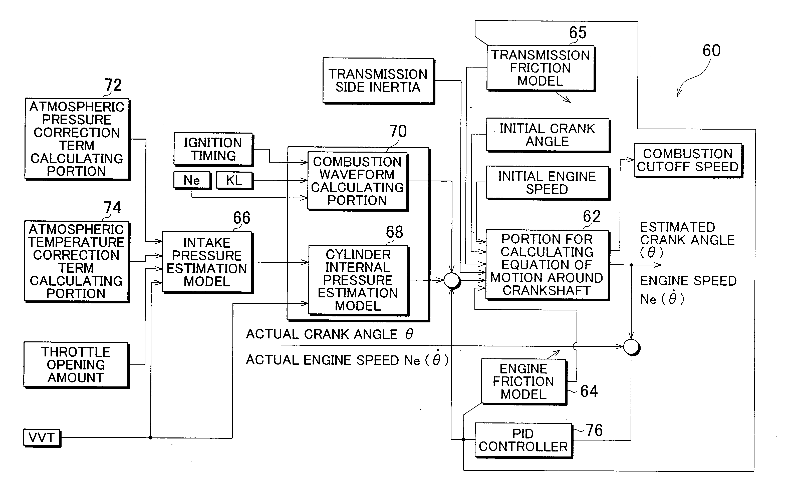
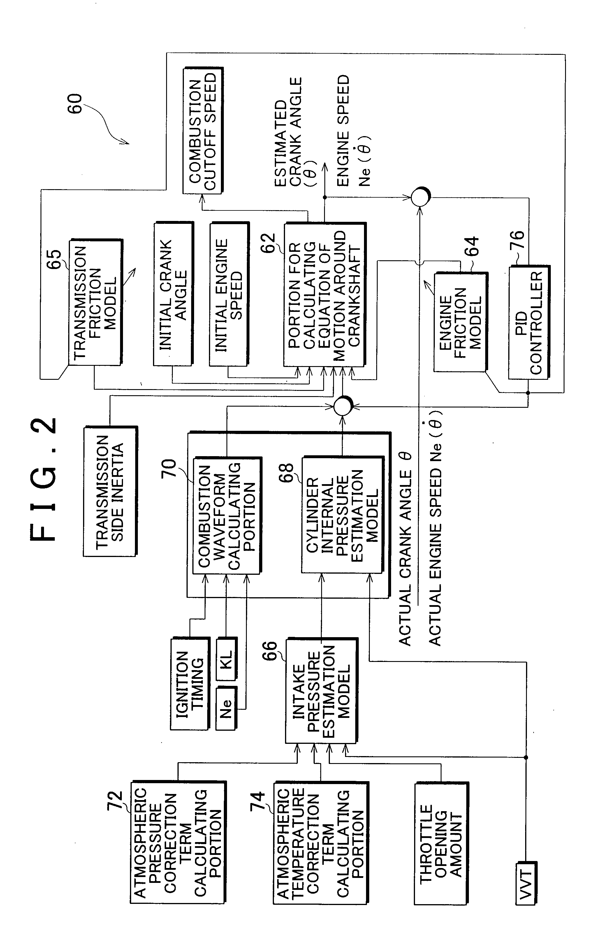
This patent describes a stopping position control apparatus and method for an internal combustion engine that can accurately estimate the position where the crankshaft of the engine stops. The apparatus includes an engine friction model and a transmission friction model that take into account the effect of friction depending on the engagement state of the clutch. The apparatus also includes a deviation contributing degree obtaining apparatus that obtains information on the degree of contribution that each model contributes to the deviation in the crankshaft stopping position. A friction correcting apparatus can also be included to correct the friction models based on information obtained while the clutch is engaged. The apparatus and method can improve the accuracy and reliability of the control for automatically stopping and restarting the engine.

Problems solved by technology

The effect of friction on the crankshaft may cause the crankshaft stopping position to be off from the target stopping position when automatically stopping the internal combustion engine.

Method used


Image

  • Stopping position control apparatus and stopping position control method of internal combustion engine
  • Stopping position control apparatus and stopping position control method of internal combustion engine
  • Stopping position control apparatus and stopping position control method of internal combustion engine

Examples


first example embodiment

[0030][Structure of the Apparatus According to a First Example Embodiment]

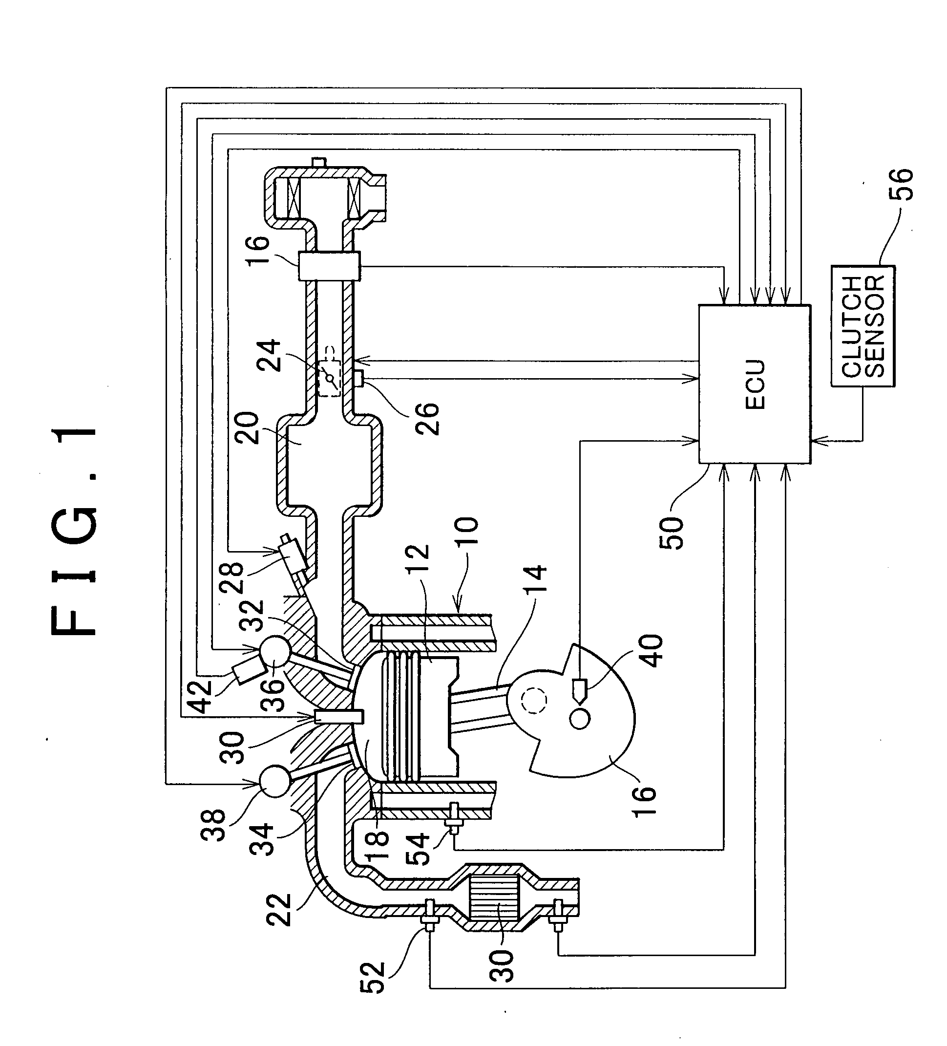
[0031]FIG. 1 is a view of the structure of an internal combustion engine 10 to which a stopping position control apparatus of an internal combustion engine according to a first example embodiment of the invention is applied. The system of this example embodiment includes the internal combustion engine 10, which in this case, is an inline four cylinder engine. A piston 12 is provided in each cylinder. The piston 12 is connected to a crankshaft 16 via a connecting rod 14. Also, a combustion chamber 18 is formed above the top portion of the piston 12 in each cylinder of the internal combustion engine 10. This combustion chamber 18 is communicated with an intake passage 20 and an exhaust passage 22.

[0032]A throttle valve 24 is provided in the intake passage 20. This throttle valve 24 is an electronic throttle valve that can control the throttle opening amount independently from an accelerator depression amount. A ...

modified example embodiment

[0143]Next, a modified example embodiment will be described with reference to FIG. 10. The system of this modified example embodiment is realized by having the ECU 50 execute the routine in FIG. 10 instead of the routine in FIG. 7 using the hardware structure shown in FIG. 1 and the engine model 60 shown in FIG. 2.

[0144][Friction Learning According to the Modified Example Embodiment]

[0145]The internal combustion engine 10, the engine oil, the transmission, and the transmission fluid do not always degrade in sync so there may be some variation in the degree of degradation in the internal combustion engine 10 and the transmission. Such variation may affect the learning accuracy and learning speed of the engine friction and the transmission friction which are necessary to precisely estimate the crankshaft stopping position.

[0146]Therefore, in this example embodiment, regardless of whether the clutch is engaged or disengaged, learning of the transmission friction is separate from the co...


PUM


Abstract

A stopping position control apparatus of an internal combustion engine includes an engine friction model for calculating the friction around a crankshaft, which calculates friction in the internal combustion engine, and a transmission friction model for calculating the friction around the crankshaft, which calculates friction in a transmission. When a clutch arranged between the internal combustion engine and the transmission is engaged, a crankshaft stopping position is calculated based on the friction calculated by both the engine friction model and the transmission friction model.

Description

INCORPORATION BY REFERENCE[0001]The disclosures of Japanese Patent Application Nos. 2006-091246 and 2006-214447 filed on Mar. 29, 2006 and Aug. 7, 2006, respectively, each including the specification, drawings and abstract are incorporated herein by reference in their entireties.BACKGROUND OF THE INVENTION[0002]1. Field of the Invention[0003]The invention relates to a stopping position control apparatus and stopping position control method of an internal combustion engine. More particularly, the invention relates to a stopping position control apparatus of an internal combustion engine to which control for automatically stopping and restarting the internal combustion engine when a vehicle temporarily stops can be applied, as well as a control method thereof.[0004]2. Description of the Related Art[0005]Japanese Patent Application Publication No. JP-A-2004-293444, for example, describes a starting apparatus of an engine which executes control (eco-run control) for automatically stoppi...

Claims


Application Information

Patent Timeline
Patent Type & Authority Applications(United States)
IPC IPC(8): F16D48/06G06F19/00B60K26/00F02D17/00F02D29/00F02D29/02F02D45/00
CPCF02D41/009F02D41/042Y10T477/6392F02D2200/1006Y10T477/747F02D2041/0095
Inventor ADACHI, NORIYASU
Owner TOYOTA JIDOSHA KK
Learn More