
Biomolecular interaction analyzer

a biomolecular interaction and analyzer technology, applied in the field of analyzers, can solve the problems of difficult parallelization of the analyzer and the purpose of detecting a plurality of samples, and achieve the effects of preventing contamination of samples, shortening the time taken, and facilitating preparation

Inactive Publication Date: 2007-10-04
HITACHI LTD
View PDF3 Cites 0 Cited by
  • Summary
  • Abstract
  • Description
  • Claims
  • Application Information

AI Technical Summary

Benefits of technology

[0014]It is an object of the present invention to provide a biomolecular interaction analyzer which makes it possible to simultaneously perform measurement on a large number of different kinds of objects to be measured.
[0016]The present invention makes it possible to simultaneously measure interactions among a plurality of samples to be measured in a plurality of sensor areas by means of an optical device such as a CCD array sensor. The present invention also makes it possible to prevent a sample from being contaminated and to facilitate a preparation by separating the sensor and the samples to be measured depending on each measurement condition and by achieving a simple change thereof, thus shortening time taken for the measurement of a large number of samples under many kinds of conditions.

Problems solved by technology

In spite of an increasing need for such a measurement of the interaction between biomolecules in recent years, the down-sizing of the analyzer and the parallelization thereof for the purpose of detecting a plurality of samples have been difficult to achieve.

Method used


Image

  • Biomolecular interaction analyzer
  • Biomolecular interaction analyzer
  • Biomolecular interaction analyzer

Examples


example 1

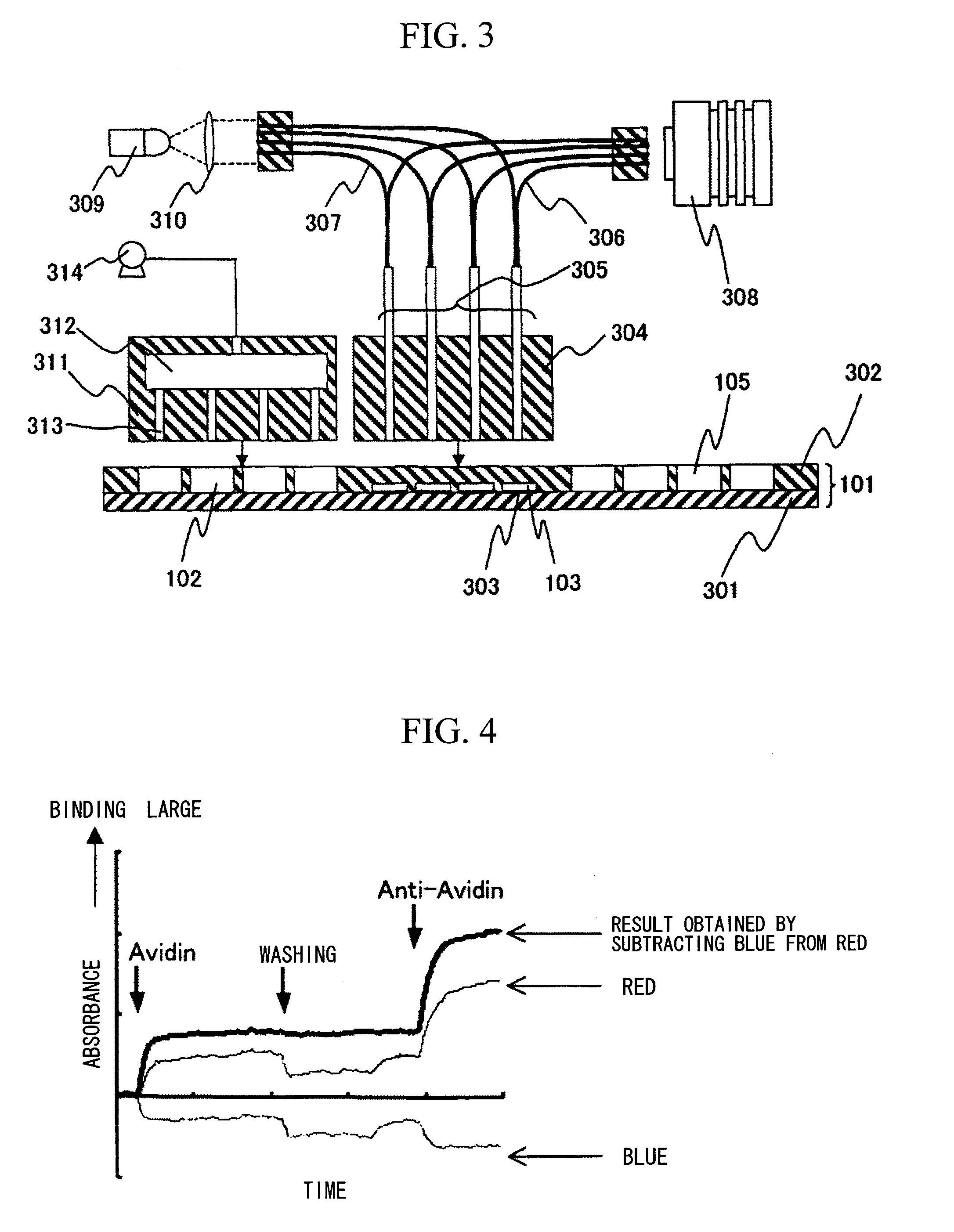
[0026]A first example according to the present invention is described with reference to FIGS. 1 to 4.

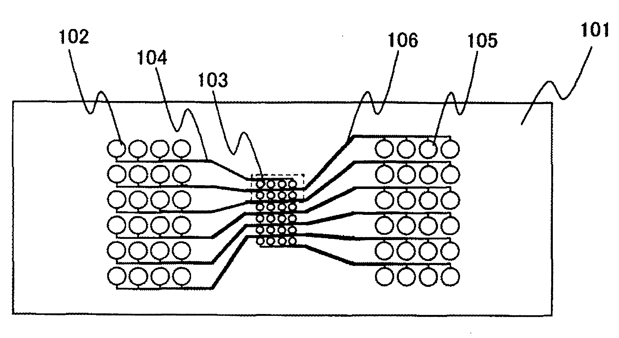
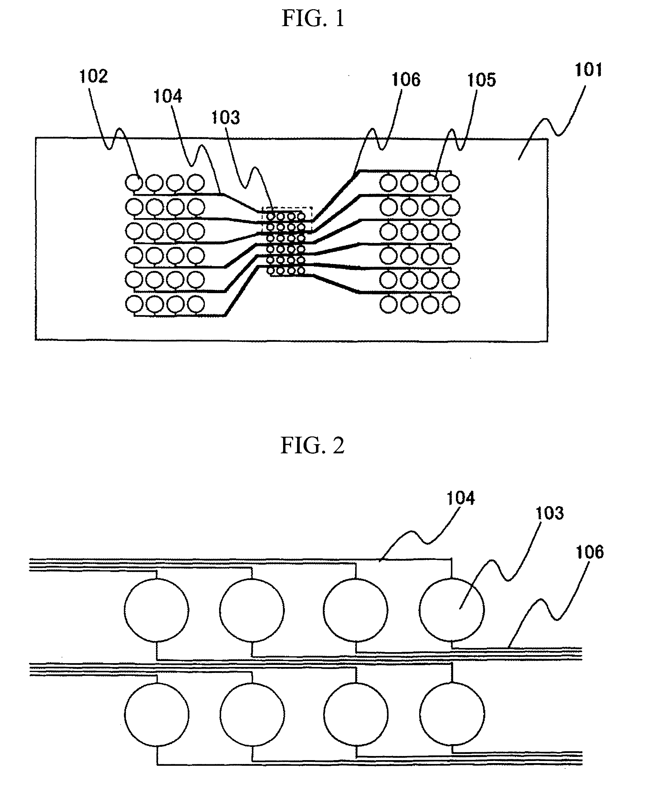
[0027]FIG. 1 shows a schematic structure of a measurement chip according to the present invention. The measurement chip 101 includes a plurality of sample solution holding areas 102, a plurality of measurement areas 103 and a plurality of measured sample solution holding areas 105. The sample solution holding areas 102, which are disposed in a two-dimensional array, temporarily hold sample solutions to be measured. The measurement areas 103, which are disposed in a two-dimensional array, have noble metal fine particle sensors formed therein, and the measured sample solution holding areas 105, which are disposed in a two-dimensional array, hold measured sample solutions after measurement. The sample solution holding areas 102 are respectively connected to the measurement areas 103 via corresponding injection flow paths 104, and the measurement areas 103 are respectively connected to t...

example 2

[0037]A second example will be described with reference to FIGS. 5 and 6.

[0038]FIG. 5 shows a schematic structure of a measurement chip. A measurement chip 501 includes an area 503 for temporarily holding measurement sample solution, a flow path 505 in which a plurality of noble metal fine particle sensor areas 502 are formed in an array pattern, and an area 504 for holding the measured sample solution after measurement. The sample solution holding area 503 and the measured sample solution holding area 504 are connected with each other via the flow path 505.

[0039]FIG. 6 shows a schematic construction of an interaction analyzer. As in Example 1, the measurement chip 501 includes a measurement chip substrate 601 and a measurement chip top board 602. On the measurement chip substrate 601, the noble metal fine particle sensor areas 502 are formed, and on the measurement chip top board 602, the sample solution holding area 503, the measured sample solution holding area 504, and the flow ...


PUM


Abstract

Obtained is a biomolecular interaction analyzer which is capable of simultaneously measuring a large number of many kinds of samples. The biomolecular interaction analyzer is an analyzer for measuring biomolecular interactions, which includes a measurement chip and a color CCD array. The measurement chip includes a plurality of measurement areas in each of which a fine particle sensor coated with a noble metal is formed. In the color CCD array, two-dimensionally arrayed light receiving elements respectively for measuring optical properties of the measurement areas are utilized.

Description

CLAIM OF PRIORITY[0001]The present application claims priority from Japanese application JP 2006-92749 filed on Mar. 30, 2006, the content of which is hereby incorporated by reference into this application.BACKGROUND OF THE INVENTION[0002]1. Field of the Invention[0003]The present invention relates to an analyzer for analyzing molecular interactions, which adopts a biosensor, the analyzer being used for biochemical study, pharmaceutical development, medical diagnosis, and food inspection.[0004]2. Description of the Prior Art[0005]Conventional sensors of this type include a sensor in which Surface Plasmon Resonance (SPR) is utilized. The surface plasmon is a wave of condensation and rarefaction of free electrons which travel on an interface between metallic thin film and a dielectric. Since the surface plasmon is largely influenced by a dielectric constant at the interface, it is used as a detection principle for an immunosensor, a gas sensor and the like.[0006]FIG. 7 shows a specifi...

Claims


Application Information

Patent Timeline
IPC IPC(8): C12M1/34G06T7/40
CPCB01L3/0293B01L3/5025B01L3/502715G01N21/554B01L2300/0822B01L2400/0487B01L2300/0816
Inventor MIYAMOTO, TETSUROHAKARI, MAMITOGASHI, SHIGENORI
Owner HITACHI LTD
Learn More