
Injection apparatus and control method thereof

a technology of injection apparatus and control method, which is applied in the direction of auxillary shaping apparatus, manufacturing tools, food shaping, etc., can solve the problems of extending the time of injection operation, affecting the vulcanization effect of raw materials, and the interior of products cannot have the desired elasticity, etc., to achieve uniform and rapid vulcanization of raw materials

Inactive Publication Date: 2007-10-04
SAMSUNG GWANGJU ELECTRONICS CO LTD
View PDF2 Cites 4 Cited by
  • Summary
  • Abstract
  • Description
  • Claims
  • Application Information

AI Technical Summary

Benefits of technology

[0017]The present disclosure has been made in view of the above and other problems, and an aspect of the present disclosure is to provide an injection apparatus, which enables uniform and rapid vulcanization of a raw material injected into an injection mold.
[0018]It is another aspect of the present disclosure to provide the injection apparatus, which can prevent local vulcanization of the raw material within the injection mold so that an injected product can be free from defects such as flow-marks on an outer surface thereof, thereby improving a quality of the product.
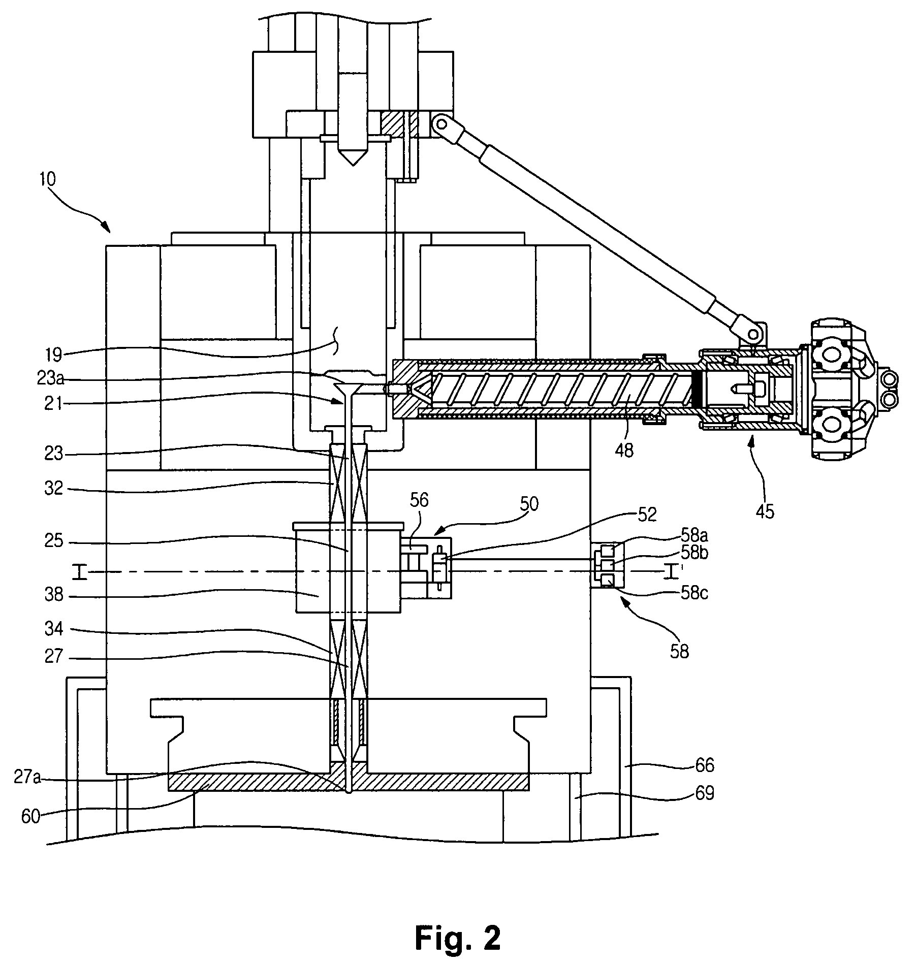
[0026]The resonance chamber may surround the second nozzle, and cause the microwaves induced into the resonance chamber to be resonated therein and be then irradiated to the second nozzle.
[0028]The injection apparatus may further comprise a temperature controller around the nozzle to prevent a rapid increase in temperature of the raw material passing through the nozzle.

Problems solved by technology

However, the heat cannot be efficiently transferred to a portion of the raw material near a central region of the mold, causing a temperature deviation in the raw material.
Hence, since it is necessary to wait until the heat is transferred to the central region of the mold in order to allow the vulcanization of the raw material to occur in an overall region within the mold, there is a problem of extending a time for injection operation.
In addition, although an outer surface of an injected product may have a desired elasticity even with insufficient transfer of heat into the central region of the raw material, an interior of the product cannot have the desired elasticity, failing to achieve a uniform quality.
Furthermore, a low thermal conductivity of the raw material causes local overheating of the raw material within the mold, thereby causing local acceleration of vulcanization, which results in defects such as flow-marks on an outer surface of the product.

Method used


Image

  • Injection apparatus and control method thereof
  • Injection apparatus and control method thereof
  • Injection apparatus and control method thereof

Examples


Embodiment Construction

[0045]Reference will now be made in detail to the embodiments of the present disclosure, examples of which are illustrated in the accompanying drawings, wherein like reference numerals refer to like elements throughout the drawings. The embodiments are described below to explain the disclosure by referring to the figures.

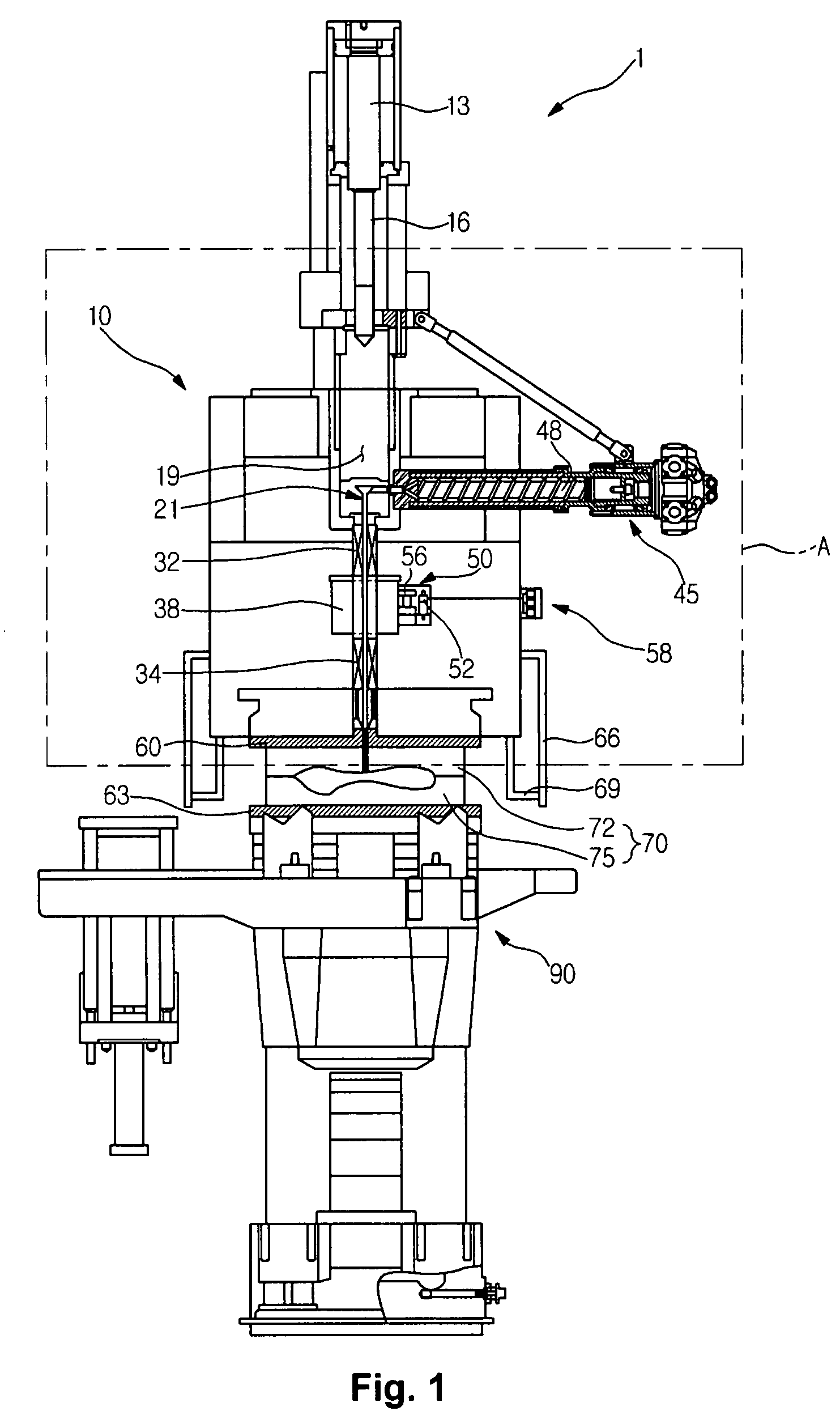
[0046]FIGS. 1 to 4 show an injection apparatus according to a first embodiment of the present disclosure. Referring to FIG. 1, an injection apparatus 1 of the present disclosure comprises an upper frame 10 having an injection chamber 19 defined therein to receive a raw material upon injection of the raw material, a lower frame 90, an injection plunger 16 positioned above the injection chamber 19, and a cylinder 13 to cause a vertical movement of the injection plunger 16.

[0047]A raw material feeder 45 is positioned at one side of the upper frame 10 while being communicated with one side of the injection chamber 19 to feed the raw material into the injection chamber 1...


PUM

PropertyMeasurementUnit
Temperatureaaaaaaaaaa
Pressureaaaaaaaaaa
Poweraaaaaaaaaa

Abstract

Disclosed herein is an injection apparatus and control method thereof. The apparatus comprises a nozzle to guide a raw material to flow into an injection mold, a microwave transmission part positioned at a portion of the nozzle, and a microwave generation part positioned near the nozzle to generate and irradiate microwaves to the microwave transmission part. With this structure, vulcanization of the raw material injected into the injection mold occurs uniformly and rapidly within the injection mold, thereby improving a quality of an injection molded product while increasing a speed of injection operation.

Description

CROSS-REFERENCE TO RELATED APPLICATIONS[0001]This application claims the benefit under 35 U.S.C. §119 of Korean Patent Application No. 2006-0028503, filed on Mar. 29, 2006 in the Korean Intellectual Property Office, the disclosure of which is incorporated herein by reference.BACKGROUND OF THE INVENTION[0002]1. Field of the Invention[0003]The present disclosure relates to an injection apparatus, and, more particularly, to an injection apparatus, which allows vulcanization of a material injected into an injection mold to occur uniformly and rapidly within the injection mold, thereby improving a quality of an injection molded product while increasing a speed of an injection operation.[0004]2. Description of the Related Art[0005]An injection apparatus refers to an apparatus which produces an article having a desired shape by injecting a raw material, such as a rubber or plastic material, having fluidity at high temperatures, into an injection mold having a predetermined shape correspond...

Claims


Application Information

Patent Timeline
IPC IPC(8): B29C45/03B29C45/20
CPCB29C33/06B29C45/2737B29C45/34B29C45/78B29C2035/0855B29C2791/006B29K2021/00B29C2945/7621B29C2945/76381B29C2945/76518B29C2945/76688B29C2945/76859B29C2945/7604B29C45/46B29C45/76
Inventor HAN, YOUNG GILPARK, JONG WOON
Owner SAMSUNG GWANGJU ELECTRONICS CO LTD
Learn More