
System and method for pre-cooling of buildings

Active Publication Date: 2007-10-04
NIGHTBREEZE
View PDF21 Cites 132 Cited by
  • Summary
  • Abstract
  • Description
  • Claims
  • Application Information

AI Technical Summary

Benefits of technology

[0010] It is an object of this invention to provide a method of nighttime pre-cooling of a building that reduces energy costs and minimizes energy consumption during periods of peak electric demands.
[0014] A further object of this invention is to provide a method of nighttime pre-cooling of a building that utilizes a variable speed fan motor to minimize the consumption of energy during the operation of an outside air ventilation system.
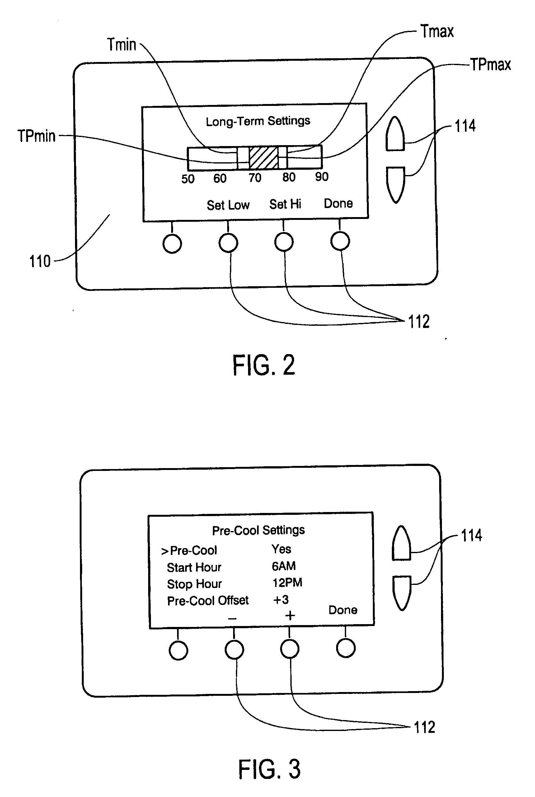
[0015] The invention utilizes electronic components that include a user input device for use in selecting an indoor low temperature limit and an indoor high temperature limit; and for use in displaying a range of predicted indoor temperatures for a future period. The user input device provides feedback to the user on user-input settings that provide acceptable levels of comfort and optimal energy consumption.

Problems solved by technology

Utilities and other power providers are striving to reduce electricity use during periods of peak electricity demand because of the high cost of on-peak power and the risk of brown-outs stemming from capacity shortages.
Recent studies have predicted an increased rate of power outages in future years based on the inability of power grids to supply increasing power demands.
Utility peak capacity shortages are reaching crisis proportions in many areas of the U.S., with utilities resorting to programs for cycling air conditioning equipment off during periods of high peak demand.
Conventional thermostats have no provisions for preventing operation specifically during utility peak power use periods or during power shortage alerts.
These systems do not provide for optimal reduction of electricity demand during peak afternoon periods.
Also, these controls provide no feedback to encourage lower indoor temperature settings that would avert air conditioner use on hot days.
However, a user will limit this low temperature to maintain an acceptable level of comfort.
Too much pre-cooling uses excessive energy and compromises comfort; too little results in excessive peak period energy use.
Conventional methods and control strategies for pre-cooling commercial and residential buildings do not provide for optimal reduction of electricity demand during peak afternoon periods.

Method used


Image

  • System and method for pre-cooling of buildings
  • System and method for pre-cooling of buildings
  • System and method for pre-cooling of buildings

Examples


Embodiment Construction

[0022] Embodiments of the present invention provide methods and controls for nighttime pre-cooling of a building. A description of these embodiments is provided with reference to drawing FIGS. 1-5.

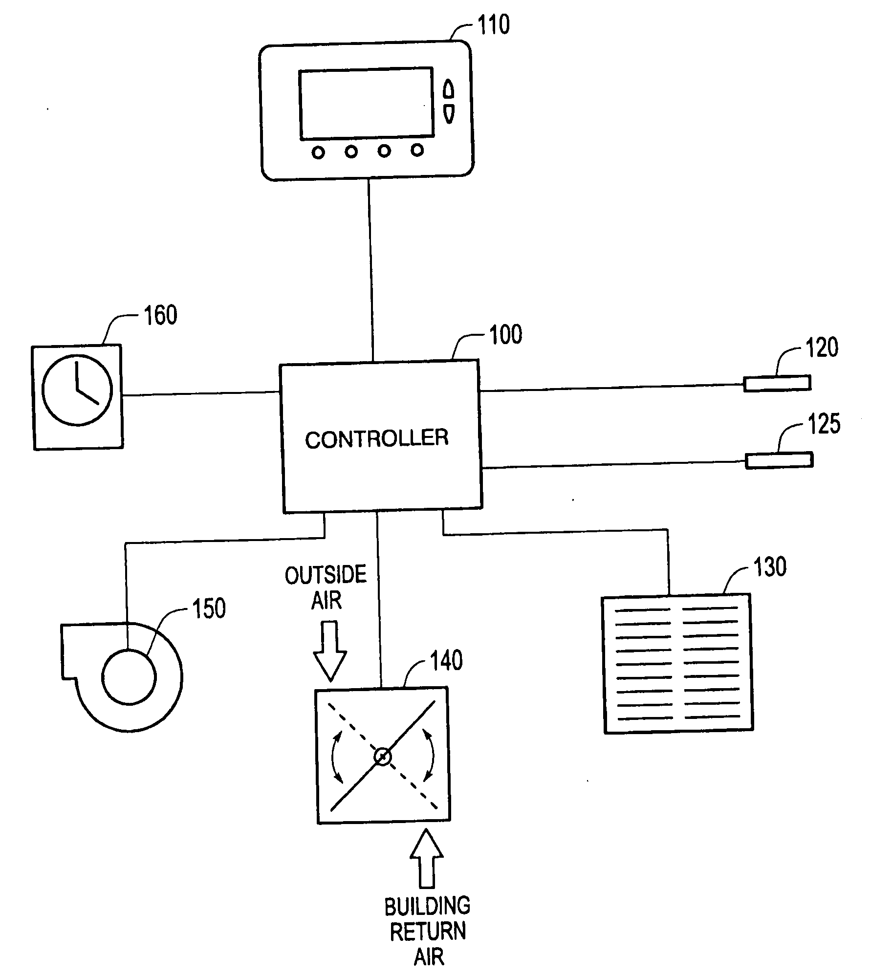
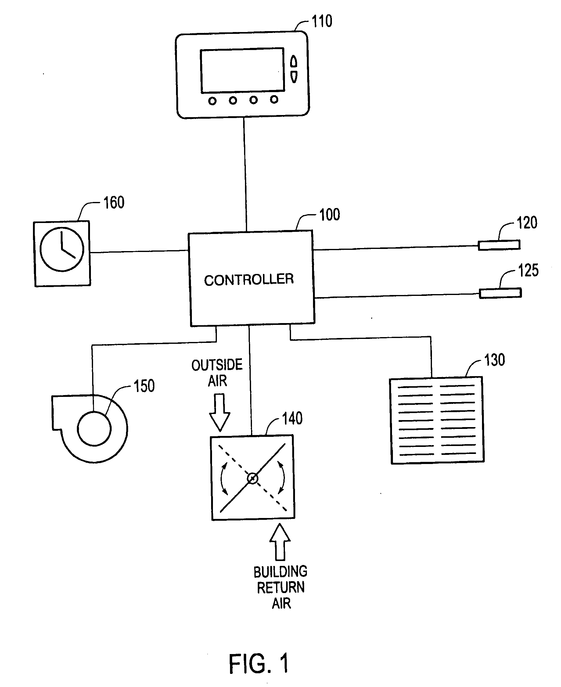
[0023]FIG. 1 provides a schematic diagram of an integrated outside air ventilation cooling system and a vapor compression cooling system that may be utilized to practice an embodiment of the present invention. Outside air ventilation cooling systems and vapor compression cooling systems having other configurations known in the art, including integrated systems and separate systems may alternatively be utilized to practice embodiments of the present invention.

[0024]FIG. 2 provides a diagram of an input device, also referred to as a “user interface” or a “wall display unit,” that displays a first set of user-selected and operational settings. FIG. 3 provides another diagram of an input device that displays a second set of user-selected operational settings.

[0025] As shown in FIGS. 4 and 5...


PUM


Abstract

A method is provided for nighttime pre-cooling of a building comprising inputting one or more user settings, lowering the indoor temperature reading of the building during nighttime by operating an outside air ventilation system followed, if necessary, by a vapor compression cooling system. The method provides for nighttime pre-cooling of a building that maintains indoor temperatures within a comfort range based on the user input settings, calculated operational settings, and predictions of indoor and outdoor temperature trends for a future period of time such as the next day. The method reduces energy costs and minimizes energy consumption during periods of peak electric demand.

Description

[0001] This is a Continuation of application Ser. No. 09 / 802,883 filed Mar. 12, 2001. The entire disclosure of the prior application is hereby incorporated by reference herein in its entirety.BACKGROUND OF INVENTION [0002] 1. Field of Invention [0003] This invention relates to methods and controls for providing outside air ventilation and vapor compression cooling to commercial and residential buildings, and more specifically, for nighttime pre-cooling of commercial and residential buildings utilizing outside air ventilation and vapor compression cooling. [0004] 2. Description of Relevant Art [0005] Utilities and other power providers are striving to reduce electricity use during periods of peak electricity demand because of the high cost of on-peak power and the risk of brown-outs stemming from capacity shortages. Recent studies have predicted an increased rate of power outages in future years based on the inability of power grids to supply increasing power demands. Utility peak ca...

Claims


Application Information

Patent Timeline
IPC IPC(8): G05D23/00F24F11/00F24F13/14G05D23/19
CPCF24F11/006F24F11/0079Y02B30/746F24F2013/1473G05D23/1931F24F2011/0058F24F11/30F24F2130/00F24F2130/10F24F11/62F24F11/77Y02B30/70F24F11/56
Inventor SPRINGER, DAVID A.RAINER, LEO I.
Owner NIGHTBREEZE
Learn More