
Cordless window covering

a window covering and cordless technology, applied in the field of window coverings, can solve the problems of limiting the expansion range of the window covering, and the window covering will not remain in the desired position

Inactive Publication Date: 2007-10-04
YU FU LAI +1
View PDF42 Cites 30 Cited by
  • Summary
  • Abstract
  • Description
  • Claims
  • Application Information

AI Technical Summary

Benefits of technology

[0011] In operation, the transmission system creates a differential in the rotational displacement between the first rotary drum and the relative rotational displacement between the two ends of the spring. With similarly sized drums, the first rotary drum rotates at a greater rotational rate than the relative rotational movement of the two ends of the spring. In other words, the first rotary drum rotates faster than the spring uncoils. This results in a greater length of cord that can be deployed for a given revolution of the spring. This reduction in the spring's necessary range of extension enables the spring to remain within its linear response range throughout the movement range of the suspension cord. Accordingly, undesired variations in the force provided by the spring to balance and resist the weight of window covering are minimized.

Problems solved by technology

When the upward force exerted by the spring does not balance the downward gravitational weight of the window covering, the window covering will not remain in the desired position.
One disadvantage of the conventional cordless window covering is that the length of the coiled spring limits the range of expansion of the window covering.

Method used


Image

  • Cordless window covering
  • Cordless window covering
  • Cordless window covering

Examples


Embodiment Construction

[0028] The invention disclosed herein is susceptible to embodiment in many different forms. The embodiments shown in the drawings and described in detail below is only for illustrative purposes. The disclosure is intended as an exemplification of the principles and features of the invention, but does not limit the invention to the illustrated embodiments.

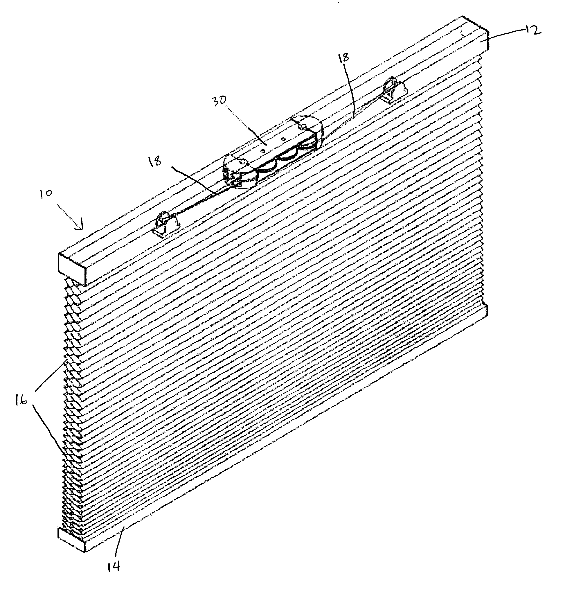
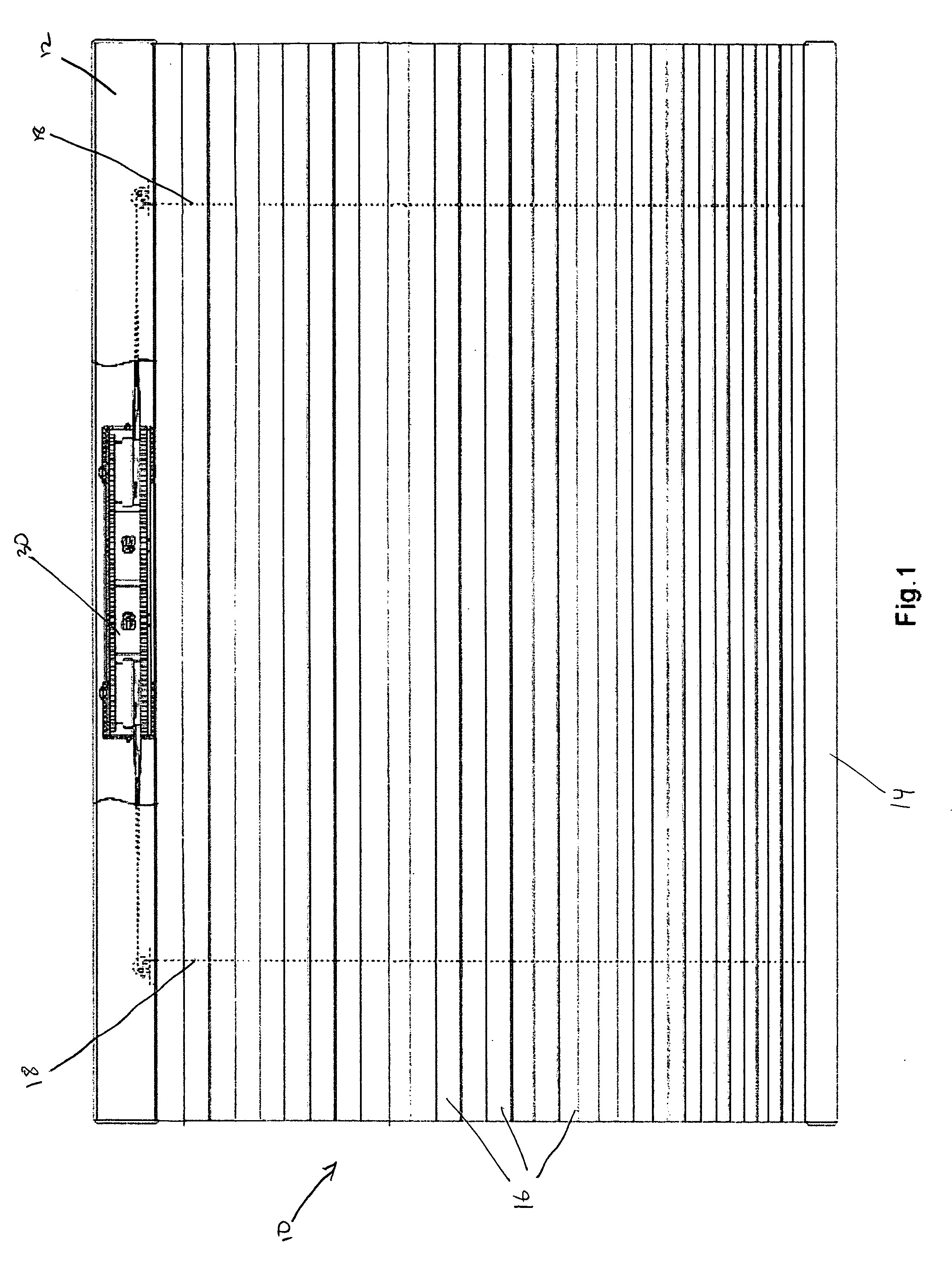
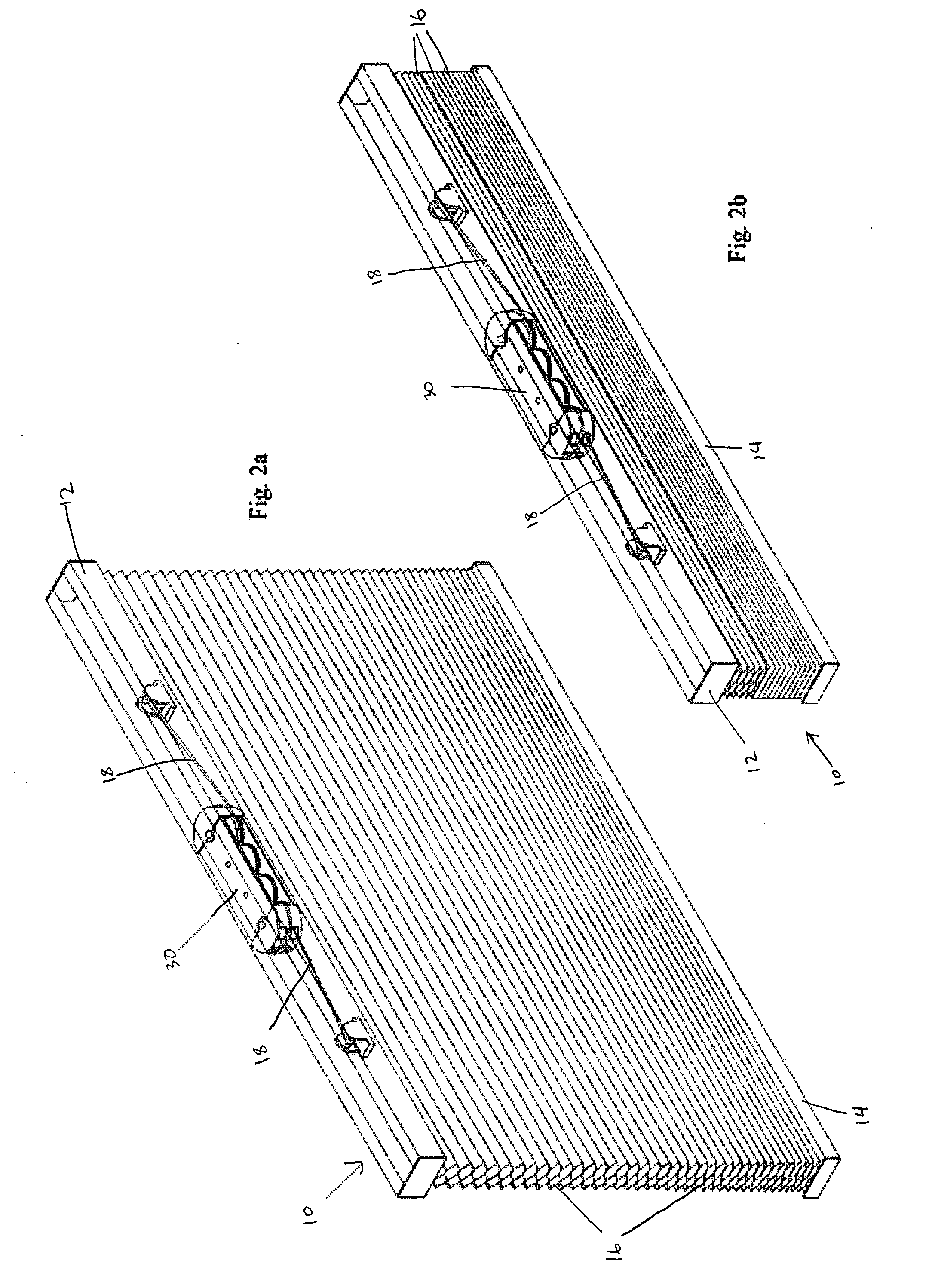
[0029] Referring to FIGS. 1, 2A and 2B, a preferred embodiment of the cordless window covering 10 according to the present invention is shown. The window covering includes a head rail 12 and a ballast element 14. Ballast element 14 may be a bottom rail and is preferably of sufficient weight to keep the window covering properly extended in the window space. The window covering 10 also has at least one light blocking element 16. These light blocking elements 16 are shown in FIGS. 2A and 2B as cellular structures, but they may also take the form of slats, sheets, or other suitable structures.

[0030] At least one suspension cord 18 con...


PUM


Abstract

A cordless window covering having a differential suspension mechanism. The suspension mechanism is composed of a first rotary drum for winding and unwinding the suspension cord of a window covering and a second rotary drum housing a spring with one end connected to the second rotary drum and the other end of the spring connected to an axle. Rotation of the first rotary drum and at least one end of the spring are linked by a transmission system. In operation, the transmission system creates a differential rotation rate between the first rotary drum and the relative rotation rate of the two ends of the spring. In this manner, a greater length of cord can be deployed for with a shorter length of spring extension.

Description

FIELD OF INVENTION [0001] This invention relates to window coverings. In particular, this invention relates to cordless window coverings where a user does not need to manipulate a control cord to raise or lower the window covering. BACKGROUND OF INVENTION [0002] Window coverings are well known in the art. A window covering typically contains a number of light blocking sections that extend horizontally across the width of a window space or other architectural opening. These light blocking sections can take a myriad of forms such as that of cellular shades, slats in a Venetian blind, and the flat sheet of a Roman shade. In these conventional window coverings, at least one suspension cord hangs down through the light blocking sections from the head rail to a ballast portion, such as a bottom rail. The window covering is raised and lowered by a user manually raising or lowering the suspension cord. After the covering is drawn to the desired height, a brake mechanism or cord lock engages...

Claims


Application Information

Patent Timeline
IPC IPC(8): E06B9/30
CPCE06B2009/3222E06B9/322
Inventor YU, FU-LAIHUANG, CHIN-TIEN
Owner YU FU LAI
Learn More