
Data port alignment of free space optical communications terminal with adaptive optics

a data port and optical communication terminal technology, applied in electromagnetic transmission, electrical equipment, transmission, etc., can solve the problems of constant changing aberrations of free-space optical communications systems, affecting the accuracy, reliability and efficiency of free-space optical communications systems, and suffering from optical aberrations of free-space optical communications links

Active Publication Date: 2007-09-27
EOS DEFENSE SYST USA INC
View PDF6 Cites 13 Cited by
  • Summary
  • Abstract
  • Description
  • Claims
  • Application Information

AI Technical Summary

Benefits of technology

[0009] The present invention overcomes the limitations of the prior art by providing a reference port. The various adaptic optics components and data ports are each aligned to the reference port, resulting in alignment of these components to each other. In one approach, a wavefront sensor in the adaptive optics system is aligned to a reference port. The data port is aligned to the reference port. In this way, alignment of the wavefront sensor and the data port is achieved.
[0010] In one implementation, a free space optical communications terminal includes a data port, an adaptive optics module which includes a wavefront sensor, a reference port and a controller. A first reference beam is transmitted from the reference port to the wavefront sensor, and the controller aligns the reference port and the wavefront sensor based on this reference beam. For example, the controller may adjust the adaptive optics module to introduce a wavefront correction that aligns the reference port and the wavefront sensor. A second reference beam is transmitted between the reference port and the data port (it could be transmitted in either direction, depending on whether the data port is a receive data port or a transmit data port). The controller aligns the reference port and the data port based on this second reference beam. For example, it may adjust a position of the data port to maximize coupling of the second reference beam between the data port and the reference port. In this way, the data port is aligned to the wavefront sensor.

Problems solved by technology

In many of these potential applications, the free-space optical communications link suffers from optical aberrations.
For example, changes in atmospheric conditions can be a significant impediment to the accuracy, reliability and efficiency of free-space optical communications systems.
Wind, heat waves, man-made pollutants and other effects can create constantly changing aberrations.
This, in turn, can degrade the quality of the optical signal that is available at the receiver, resulting in degradation of the overall quality and efficiency of the communications channel.
However, the terminal may become misaligned after it has been deployed for use in the field.
Over time, vibrations, temperature fluctuations and weather conditions can adversely affect the optical alignment of these components.
In addition, for certain applications, the terminal may be subjected to transient misalignments.
For example, if a terminal is mounted on a vehicle that is traveling over rough terrain, the sudden jolts experienced by the vehicle may continuously misalign the components, thus requiring some sort of active alignment.
In other applications, such as deployments on orbiting satellites or in remote locations, it may be difficult for a human to gain access to manually re-align the adaptive optics system and the data ports, thus favoring some sort of automatic alignment.

Method used


Image

  • Data port alignment of free space optical communications terminal with adaptive optics
  • Data port alignment of free space optical communications terminal with adaptive optics
  • Data port alignment of free space optical communications terminal with adaptive optics

Examples


Embodiment Construction

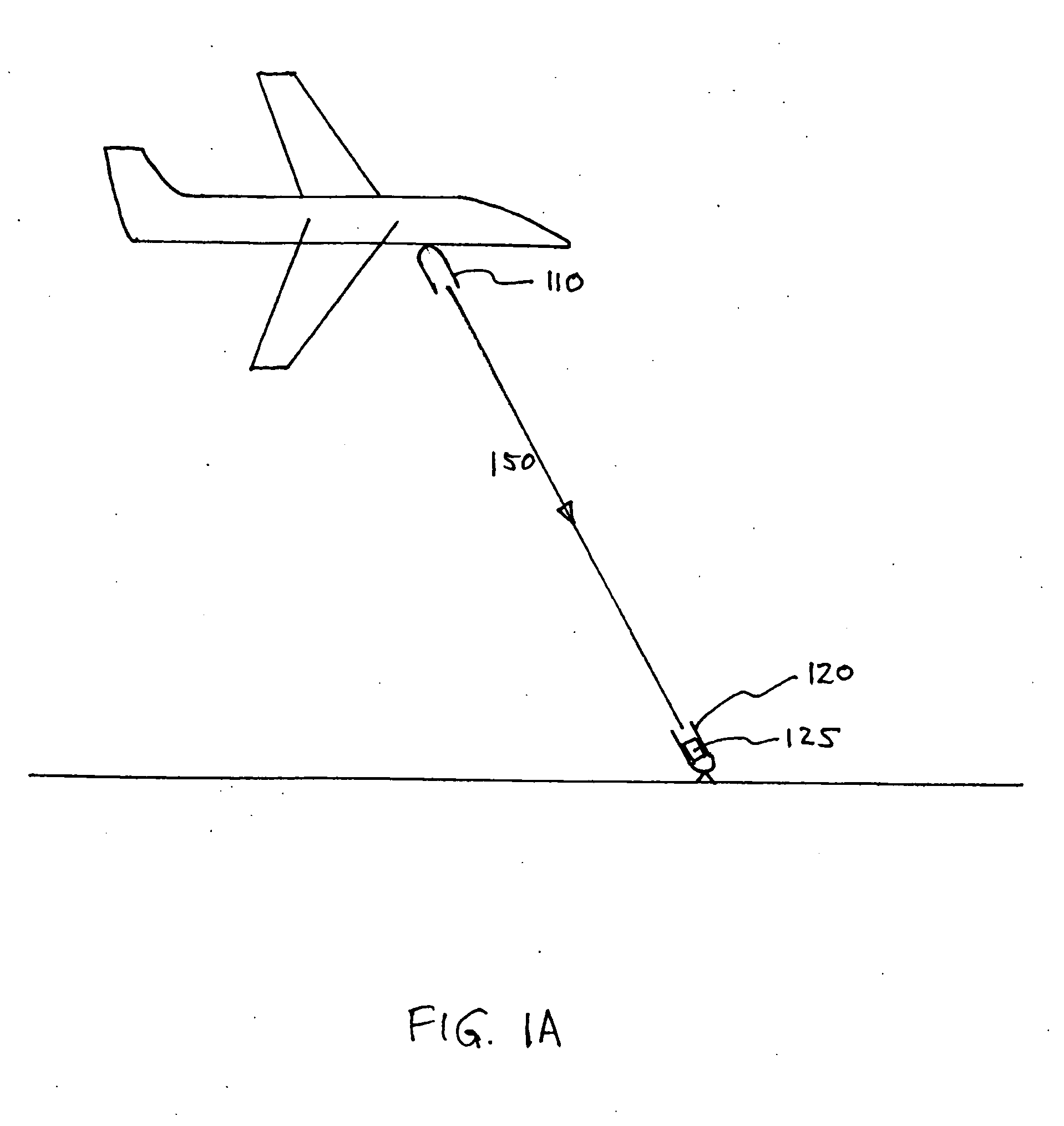
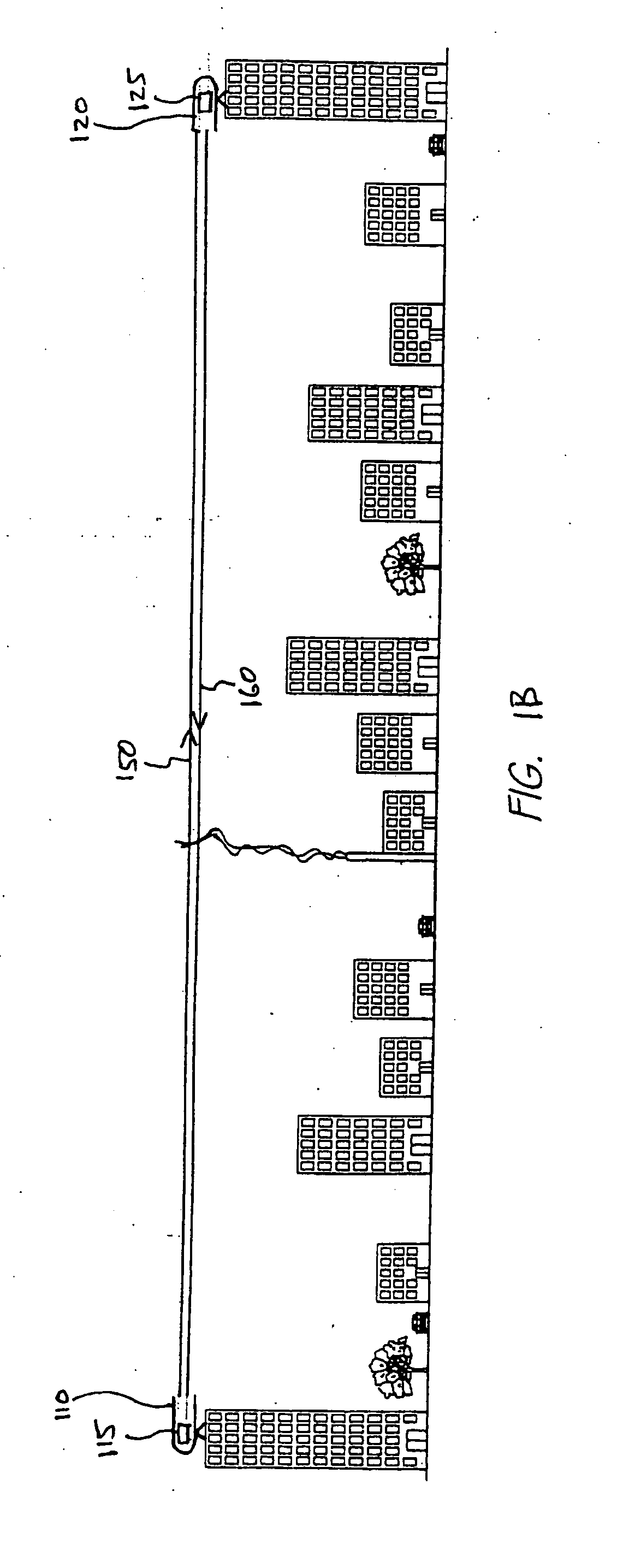
[0018]FIGS. 1A-1C are illustrations of example free-space optical (FSO) communications system using adaptive optics. The FSO communications system in FIG. 1A is designed to communicate data over a FSO data link 150 from an airborne transmitter 110 to a land-based receiver 120 which may be either stationary or mobile. For convenience, the term “transceiver” will be used to refer to modules that only transmit 110 and to modules that only receive 120, as well as to modules that both transmit and receive.

[0019] Each transceiver 110, 120 includes a telescope that is pointed at the telescope of the other transceiver. The transmitting telescope 110 typically includes components for tracking and directing an optical beam 150 to the receiving telescope 120. The receiving telescope 120 typically includes components for following and receiving the optical beam 150 from the transmitting telescope 110. Examples of components that can be used for these purposes include steering mirrors, mechanic...


PUM


Abstract

An approach for aligning an adaptive optics module and a data port in a free space optical communications terminal. A wavefront sensor in the adaptive optics system is aligned to a reference port. The data port is also aligned to the reference port. In this way, alignment of the wavefront sensor and the data port is achieved.

Description

BACKGROUND [0001] 1. Field of Invention [0002] This invention relates generally to adaptive optics systems and, more particularly, to alignment of adaptive optics systems. [0003] 2. Description of the Related Art [0004] With recent advances in technology, there is an increasing interest in the use of free-space optical communications for various applications. Compared to other communications technologies, a free-space optical communications link can have advantages of higher mobility and compact size, better directionality (e.g., harder to intercept), faster set up and tear down, and / or suitability for situations where one or both transceivers are moving. Thus, free-space optical communications links can be used in many different scenarios, including in airborne, sea-based, space and / or terrestrial situations. [0005] In many of these potential applications, the free-space optical communications link suffers from optical aberrations. For example, changes in atmospheric conditions can...

Claims


Application Information

Patent Timeline
Patent Type & Authority Applications(United States)
IPC IPC(8): H04B10/00
CPCH04B10/1121
Inventor GRAVES, J. ELON
Owner EOS DEFENSE SYST USA INC
Learn More