
Method and apparatus for shimming a magnetic field

a magnetic field and magnetic field technology, applied in the direction of instruments, measurement devices, acoustic wave reradiation, etc., to achieve the effect of reducing or eliminating this difficulty

Inactive Publication Date: 2007-09-27
SIEMENS MAGNET TECH
View PDF20 Cites 7 Cited by
  • Summary
  • Abstract
  • Description
  • Claims
  • Application Information

AI Technical Summary

Benefits of technology

[0007]A general difficulty which is encountered with shimming process is that of ensuring that shims having the correct ferromagnetic characteristics are loaded into the correct pocket locations in the shim trays, and one object of the invention is to reduce or eliminate this difficulty.
[0026]The effectiveness of the shim tray increases rapidly the closer the shim devices are disposed to the FOV. This is particularly significant for magnets such as those shown in FIG. 4, which tend to utilize a high central field, typically in excess of 0.6 T. In this case it is desirable to have the shim tray as close to the FOV as possible. However, in current constructions, the gradient coils occupy the space nearest to the FOV because the gradient coils should be positioned as far away from conducting surfaces (such as the pole tips) as possible.

Problems solved by technology

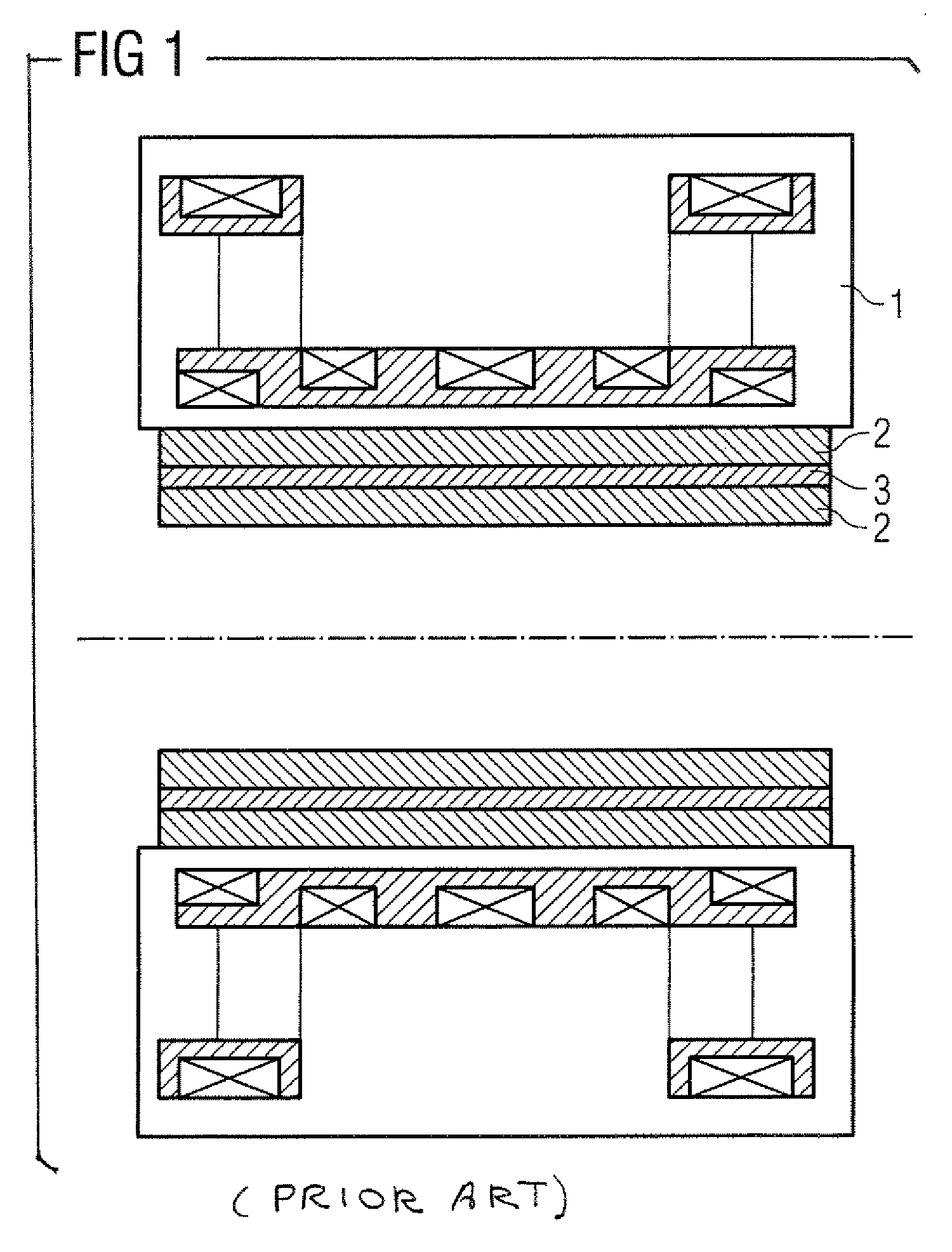
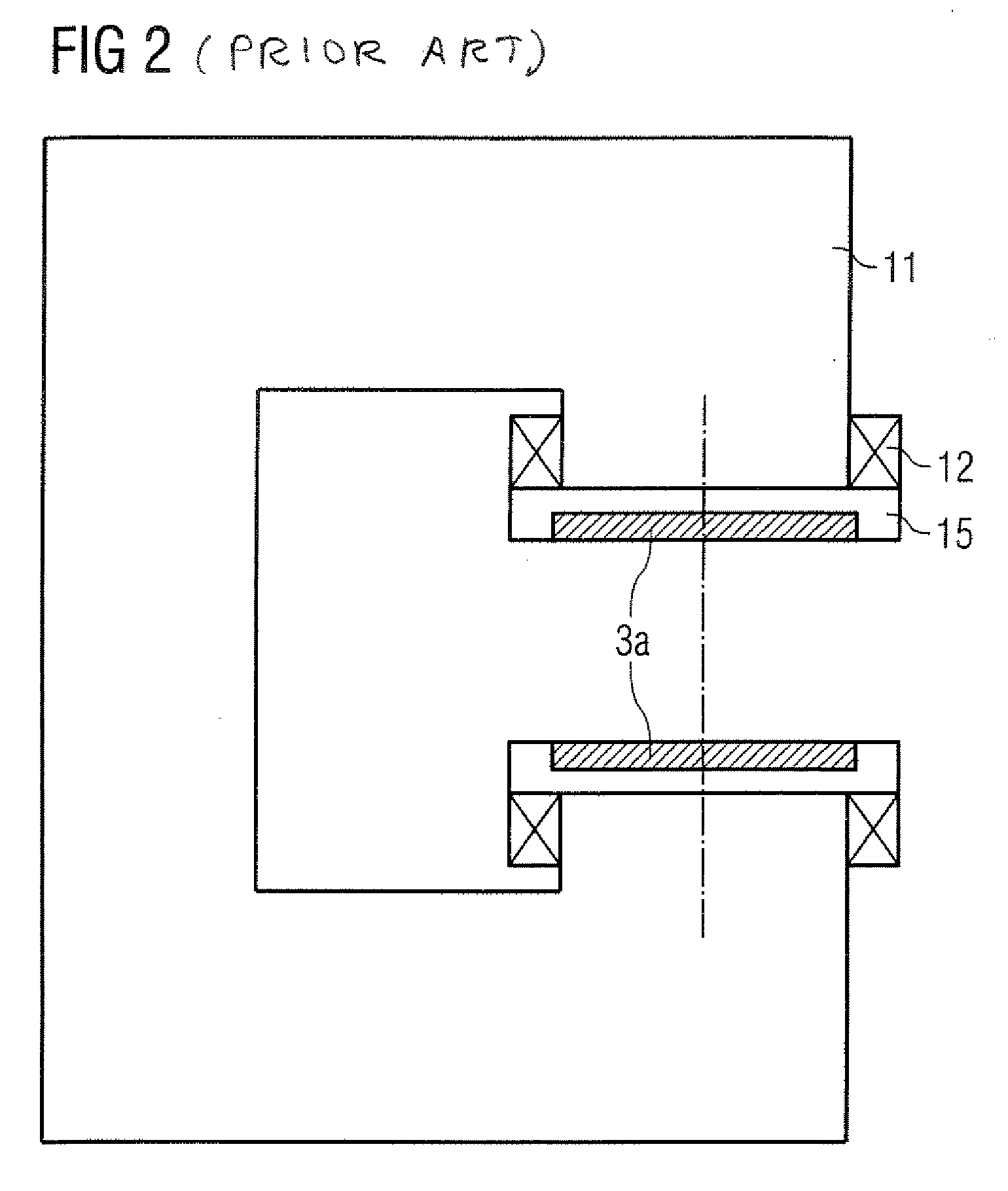
Particular difficulties arise, however, in implementing such a shimming procedure in MRI systems utilizing open magnet configurations, wherein the magnets used are non-solenoidal and have substantially flat pole-pieces. FIGS. 2, 3 and 4 show various open magnet systems, in cross-sectional view, and in general outline.

Method used


Image

  • Method and apparatus for shimming a magnetic field
  • Method and apparatus for shimming a magnetic field
  • Method and apparatus for shimming a magnetic field

Examples


Embodiment Construction

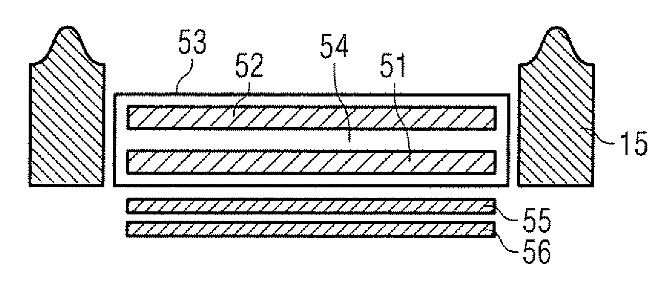
[0034]The invention will be described hereinafter in the context of an open-magnet magnetic resonance imaging (MRI) system, and it will be understood that the gradient coil assemblies in such systems are usually planar in shape. A cross section through a typical planar gradient coil set is shown in FIG. 5.

[0035]As discussed earlier, the gradient coils are formed as a so called primary coil set 51, which includes one X-direction gradient coil set, one Y-direction gradient coil set and one Z-direction gradient coil set. The stray fields of this primary gradient coil set will interact with the conducting surfaces in the pole face or the cryostat. To limit these fields, a so called secondary gradient coil set 52 may be included for some or all of the X-, Y-, or Z-directions, which includes at least a secondary coil set for the gradient coil with the most perturbing primary gradient coil, Preferably, to limit relative movement and to facilitate assembly, the primary and secondary gradien...


PUM


Abstract

An apparatus for shimming the magnetic field generated by a magnet arrangement of a magnetic resonance imaging (MRI) system, has a number of shim devices of substantially similar cross-sectional dimensions, at least some of the shim devices exhibiting differing ferromagnetic characteristics. A structure body has an elongate, tubular channel cross-sectionally dimensioned to serially receive the shim devices in a predetermined sequence to provide a required distribution of the ferromagnetic characteristics in relation to said magnetic field, the channel being of length sufficient to accommodate the shim devices serially in said predetermined sequence. The shim devices are presented at the entrance of the channel in the sequence, and are forced into the channel in the sequence by pressurized fluid directed toward the entrance.

Description

BACKGROUND OF THE INVENTION[0001]1. Field of the Invention[0002]The present invention relates to apparatus for and methods of improving the homogeneity of magnetic fields generated by the magnet arrangements utilized in magnetic resonance imaging (MRI) systems, and it relates especially, though not exclusively, to such apparatus and methods for open-magnet MRI systems. The invention also encompasses the provision of shims incorporated in such apparatus and utilized in such methods.[0003]2. Description of the Prior Art[0004]It is well known that, in order to achieve, over the field of view (FOV) of an MRI system, the high degree of field homogeneity required of the powerful magnetic fields employed, corrective measures need to be taken, since the fields as generated by the magnets tend to be inhomogeneous to an unacceptable extent.[0005]A common and effective corrective measure involves the measurement of the field characteristics to reveal its degree of spatial homogeneity, the calc...

Claims


Application Information

Patent Timeline
Patent Type & Authority Applications(United States)
IPC IPC(8): G01V3/00
CPCG01R33/3806G01R33/3873G01R33/385
Inventor FELTHAM, STUART PAULHOBBS, MATTHEWMARIE KRUIP, MARCEL JAN
Owner SIEMENS MAGNET TECH
Learn More