
Computer System

a computer system and computer technology, applied in the field of computer systems, can solve the problems of improper operation of the client server system, difficulty in recreating the environment of the computer, and difficulty in forming different applications or environments on the same server by individual users

Inactive Publication Date: 2007-09-20
HITACHI LTD
View PDF16 Cites 17 Cited by
  • Summary
  • Abstract
  • Description
  • Claims
  • Application Information

AI Technical Summary

Benefits of technology

The present invention provides a computer system that can always execute processing under the same environments no matter where the client used by the user is, and no matter what device is used. This is achieved by using a plurality of blade style computers that are coupled to a storage device over a network, where each user can freely set the environments and applications by using an arbitrary client. The management computer manages information on a correspondence of a storage area to the user who uses the storage area, and notifies the blade style computers which are used by the user of the information on the storage area corresponding to the user. This results in improved convenience for the user and reduces the device costs and the management costs of the manager.

Problems solved by technology

In the above server client system, all of the users who use the server through the clients are required to commonly use the same application program on the server, and it is difficult to constitute different applications or environments on the same server by the individual users.
Thus, the client server system is improper in conducting the operation under the environments that are changed by the users, individually.
Also, in the server client system, the client that is always used by each of the users is fixed, and it is difficult to recreate the environments of a computer which the user wishes to use at a different location (different client).

Method used


Image

  • Computer System
  • Computer System
  • Computer System

Examples


first embodiment

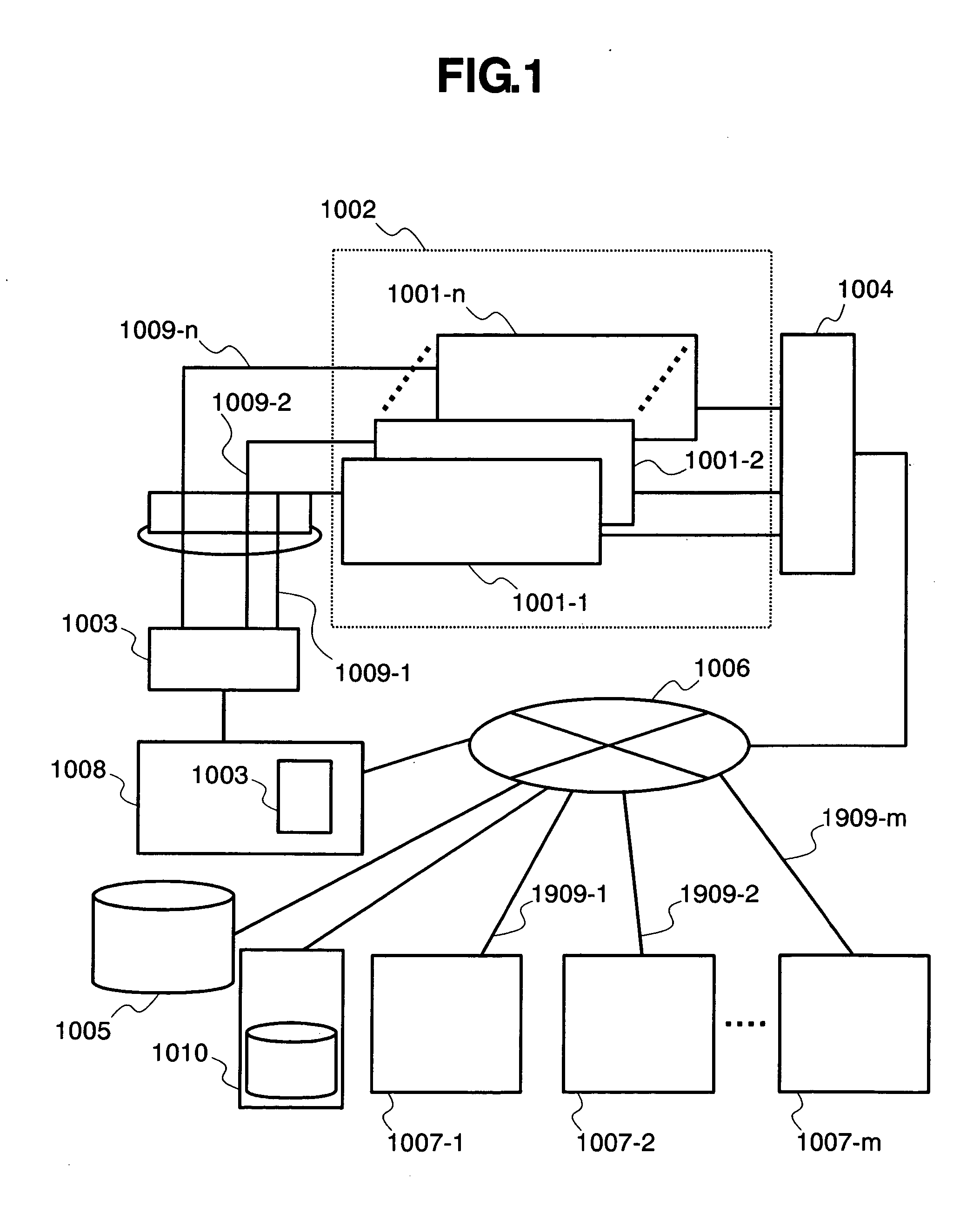
[0047]FIG. 1 is a diagram showing an example of a computer system according to a first embodiment of the present invention.

[0048] A user uses one arbitrary terminal among terminal devices (1007-1 to 1007-m). The terminal devices 1007 are coupled to a network 1006 through network wirings (1909-1 to 1909-m), respectively. The network 1006 is also coupled to a management computer 1008 and a hub device 1004. The user selects one or plural computer PCBAs from a computer device 1002 consisting of n computer PCBAs (1001-1 to 1001-n: corresponding to the blade style computers) for use. The management computer 1008 selects any of the computer PCBAs 1001 according to a predetermined rule, and then instructs the selected computer PCBA to the terminal devices 1007. Alternatively, it is possible that the user per se directly instructs any of the computer PCBAs to be used to the management computer 1008. In order to start the computer PCBA 1001 that has been selected according to the rule or the...

second embodiment

[0079]FIG. 7 is a diagram showing an example of a second embodiment. In this embodiment, the management computer 1008 directly instructs the computer PCBA 1001 to turn on the power supply whereas the power control mechanism 1003 and the management computer 1008 controls power-on to the computer PCBA 1001 in the first embodiment (FIG. 1). For that reason, the respective computer PCBAs 1001-1 to 1001-n are coupled to individual power supplies (1601-1 to 1601-n), respectively.

[0080] Specifically, the management computer 1008 instructs the computer PCBA 1001 to conduct power-on as a specific packet over the network 1006. FIG. 8 is a diagram showing a structural example of the computer PCBA 1001 that receives an instruction of power-on from the management computer 1008 in this embodiment. As compared with FIG. 2, this embodiment is different therefrom in that a communication function IF 1603 is coupled to a power control line 1602, and the power control line 1602 is coupled to an indivi...

third embodiment

[0081]FIG. 9 is a diagram showing an example of a third embodiment.

[0082] In this embodiment, the computer PCBA 1001 is controlled from not only the terminal device 1007 but also a remote terminal device (1703-1 to 1703-k) over an internet 1702. In this embodiment, a firewall gateway 1701 is located at a node at which the internet 1702 is coupled to the network 1006. The network 1006 is a dedicated network for an enterprise which is generally called “internet”. In the case of connection from the internet 1702 outside of the enterprise, it is necessary to discriminate whether the user is correct, or not, at a gate, and the firewall gateway 1701 serves to conduct the above operation. In this embodiment, the firewall gateway 1701 determines whether the user who uses the remote terminal device 1703 is correct, or not, by means of the authentication information, and allows the internal network 1006 to be used by the remote terminal device 1703 only when the user is correct (authenticati...


PUM


Abstract

A computer system can always execute processing under the same environments not depending on the terminal device that is directly used by the user, no matter where the client used by the user is, and no matter what device is used. In the computer system, one of plural computer PCBAs that do not install a hard disk device therein is selected from the terminal device, remotely controllable environments are constituted, and data is read and written from the hard disk device which are coupled to all of the computer PCBAs over a network that is used by the user.

Description

FIELD OF THE INVENTION [0001] The present invention relates to a computer system in which storage device such as a hard disk device is used by a user over a network, and more particularly to a technique by which the computer system is collectively managed, and the user uses the computer system from a device coupled over the network. DESCRIPTION OF THE RELATED ART [0002] In recent years, the price reductions of a personal computer (hereinafter referred to as “PC”) and network devices have been advanced, and business enterprises that distribute devices such as the PCs to most of employees for conducting application are being increased in number. As the business enterprises purchase an increased number of PCs with the price reduction in the PC, the number of PCs that must be subjected to maintenance operation by a device manager within the business enterprise is increased in proportion. In the present specification, the maintenance operation is directed to, for example, version up or b...

Claims


Application Information

Patent Timeline
Patent Type & Authority Applications(United States)
IPC IPC(8): G06F15/177G06F13/10G06F3/06G06F9/445G06F9/50G06F15/00
CPCH04L67/1097G06F9/46G06F9/50G06F15/16
Inventor TSUNEHIRO, TAKASHIKATO, TAKATOSHINAKAGAWA, KAZUSHIKAYASHIMA, MAKOTOKIMURA, SHINJIKOBAYASHI, IKUKO
Owner HITACHI LTD
Learn More