
Method of Controlling Compression-Ignition Internal Combustion Engine

a compression ignition and internal combustion engine technology, applied in the direction of electrical control, process and machine control, etc., can solve the problems of difficult control of the narrow stable operating range and the inability to control the ignition timing of the compression ignition internal combustion engine. to achieve the effect of easy coping

Inactive Publication Date: 2007-09-20
HONDA MOTOR CO LTD
View PDF10 Cites 35 Cited by
  • Summary
  • Abstract
  • Description
  • Claims
  • Application Information

AI Technical Summary

Benefits of technology

[0007] It is an object of the present invention to resolve the above problem and to provide a method of controlling a compression-ignition internal combustion engine capable of easily coping with a wide range of required loads with a single fuel. Means for Solving the Problems

Problems solved by technology

It is, however, hard to control the ignition timing of the compression-ignition internal combustion engine, unlike a spark-ignition internal combustion engine.
In addition, the compression-ignition internal combustion engine is susceptible to knocking in high required load of the compression-ignition internal combustion engine if a fuel of high ignitability is used and is susceptible to misfire in low required load of the compression-ignition internal combustion engine if a fuel of low ignitability is used.
Therefore, the compression-ignition internal combustion engine has a problem of a narrow stable operating range.
In this technology, however, the fuel of high ignitability and the fuel of low ignitability need be prepared individually and stored separately from each other.
The technology, however, has a problem of requiring a high-temperature and long-term reaction to generate formaldehyde by partially oxidizing the hydrocarbon such as light oil.

Method used


Image

  • Method of Controlling Compression-Ignition Internal Combustion Engine
  • Method of Controlling Compression-Ignition Internal Combustion Engine
  • Method of Controlling Compression-Ignition Internal Combustion Engine

Examples


Embodiment Construction

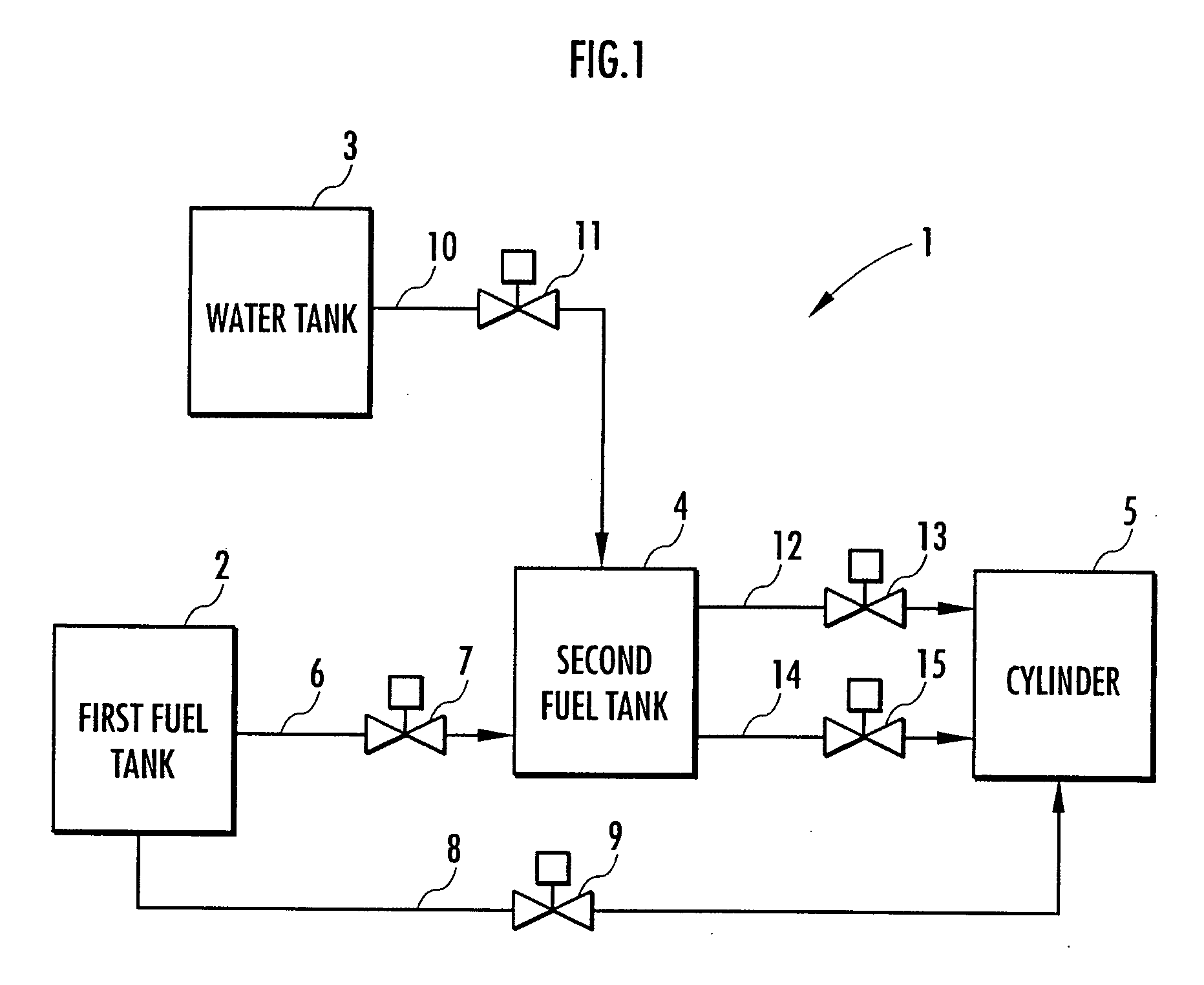
[0021] One embodiment of the present invention will be described below by using the accompanying drawings. FIG. 1 shows a block diagram illustrating a control method of this embodiment. FIG. 2 shows a graph illustrating an example of a relation between a required load of a compression-ignition internal combustion engine and a supply of a fuel to a cylinder in the control method of this embodiment.

[0022] The control method of this embodiment can be performed by the compression-ignition internal combustion engine 1 shown in FIG. 1. The compression-ignition internal combustion engine 1 includes a first fuel tank 2 for storing a blended fuel that contains alcohol and liquid hydrocarbon mixed with each other, a water tank 3 for storing water, a second fuel tank 4 for mixing the blended fuel supplied from the first fuel tank 2 with the water supplied from the water tank 3 and storing the mixture, and a cylinder 5 for compressing the fuels supplied from the first fuel tank 2 and from the ...


PUM


Abstract

There is provided a control method of a compression-ignition internal combustion engine capable of easily coping with a wide range of required loads by a single fuel. A compression-ignition internal combustion engine includes a first tank (2) for storing a blended fuel that contains alcohol and liquid hydrocarbon at predetermined percentages and a second tank (4) for mixing the blended fuel supplied from the first tank (2) with water and storing a liquid mixture of the water and the alcohol mixed with each other and the liquid hydrocarbon with the liquid mixture and the liquid hydrocarbon separated from each other, and a supply of the blended fuel stored in the first tank (2) and a supply of the liquid hydrocarbon stored in the second tank (4) are varied according to a required load of the compression-ignition internal combustion engine (1).

Description

TECHNICAL FIELD [0001] The present invention relates to a method of controlling a compression-ignition internal combustion engine. BACKGROUND ART [0002] In recent years, consideration has been given to a compression-ignition internal combustion engine typified by a homogeneous charge compression ignition engine in order to improve fuel consumption of internal combustion engines and to reduce emission. The compression-ignition internal combustion engine leads an oxygen containing gas and a fuel capable of compressed self-ignition into a cylinder and compressing the same for self-ignition. [0003] It is, however, hard to control the ignition timing of the compression-ignition internal combustion engine, unlike a spark-ignition internal combustion engine. In addition, the compression-ignition internal combustion engine is susceptible to knocking in high required load of the compression-ignition internal combustion engine if a fuel of high ignitability is used and is susceptible to misfi...

Claims


Application Information

Patent Timeline
Patent Type & Authority Applications(United States)
IPC IPC(8): G06F7/00
CPCF02B1/12F02M25/0227F02D41/0025F02M25/0228F02M25/14F02M37/0064F02M37/0088Y02T10/121Y02T10/36F02D19/0665F02D19/0671F02D19/081F02D19/084F02M25/0225F02B3/06Y02T10/12Y02T10/30
Inventor HASHIMOTO, KOHTAROGUNJI, TAKAHIROAIMOTO, KOHJIROHIKEGAWA, FUMIAKI
Owner HONDA MOTOR CO LTD
Learn More